Air-Gap-Independent Speed and Direction Sensing Using the Allegro A1262
By Stefan Kranz,
Allegro MicroSystems, LLC
Introduction
The A1262 integrated circuit is an ultrasensitive dual-channel Hall-effect latch. As with conventional dual-channel latches, the quadrature outputs of the A1262 indicate rotation direction and position/speed of a rotating ring magnet target. It is unique, however, in its use of vertical Hall technology to sense magnetic field direction in addition to amplitude.
The A1262 contains a conventional planar Hall element to derive one channel and a vertical Hall element to derive the other channel. The result is that the A1262 is capable of generating quadrature output signals (≈90° phase difference) where the phase separation is largely independent of the air gap, ring magnet size, or pole spacing. This provides an unprecedented level of flexibility for the system designer in selecting the ring magnet and its position and orientation relative to the sensor. Its small (SOT23-5) package replaces a pair of conventional Hall-effect latches, saving space and component count.
Case Studies
This application note will focus on two of the many possible system configurations. In both cases, the A1262LLHLT‑T device is assumed to use the Z sensing direction for the planar Hall element, and Y for the vertical Hall element (see Figure 1). An alternative version of the A1262, the A1262LLHLT‑X‑T, is also available with sensitivity in the Z and X directions. Detailed information on the A1262 can be found in the A1262 datasheet and other related application notes.
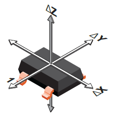
Figure 1: A1262 Sensing Directions
In both cases, the target is a ferrite ring magnet with identical overall dimensions. In Case 1, the magnet is a multipole ring magnet. In Case 2, it is a diametrically magnetized (1 pole-pair) ring magnet (See Photo 1).
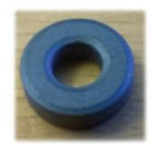
Photo 1: Ring Magnet
Case 1: Multipole Ring Magnet
In this case, the target is a ring magnet with the following characteristics:
Outer diameter: 13 mm
Inner diameter: 6 mm
Height: 4 mm
Pole-pairs: 4
Material: Ferrite Y10T, BR: ≥ 0.2 T
Magnetization: Radial
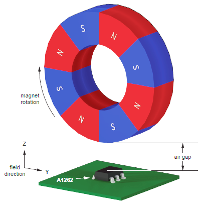
Figure 2: Mechanical Configuration for Case 1
The radial and tangential magnetic fields versus air gap around the Case 1 ring magnet are shown in Figure 3 and Figure 4. The radial field component excites the A1262 planar Hall element and is shown as the Z direction. The vertical Hall element responds to the tangential magnetic field; this is displayed as Y direction.
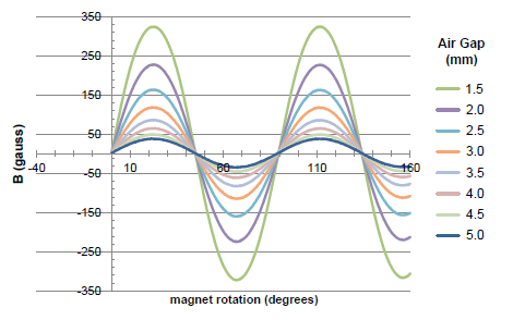
Figure 3: Radial B-Field Multipole Ring Magnet vs. Air Gap
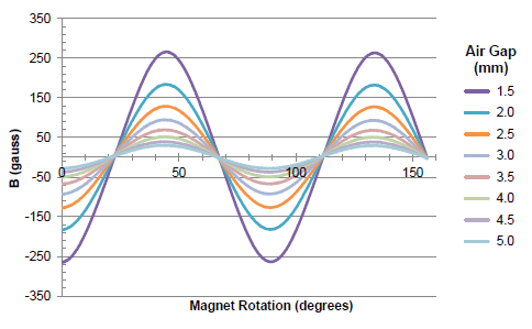
Figure 4: Tangential B-Field Multipole Ring Magnet vs. Air Gap
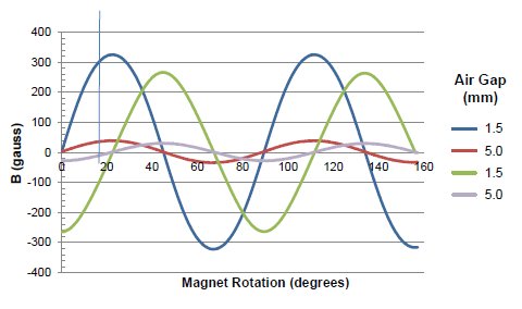
Figure 5: Radial / Tangential B-Field Multipole Ring Magnet vs. Air Gap
As shown in Figure 3 and Figure 4, the locations of the magnetic peaks of each of the two channels are very consistent relative to the other channel. There is very little variation with air gap. Figure 5 illustrates this more clearly by showing only the results for the minimal and maximal air gaps, 1.5 and 5.0 mm, respectively.
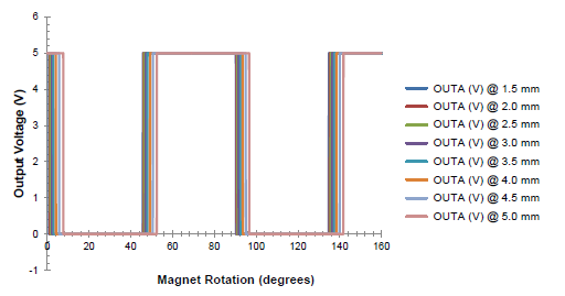
Figure 6: A1262 Multipole Ring Magnet OUTA (radial) vs. Air Gap
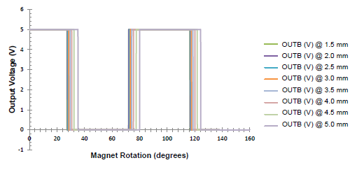
Figure 7: A1262 Multipole Ring Magnet OUTB (tangential) vs. Air Gap
Figure 6 and Figure 7 show the magnetic switching behavior of the two sensor outputs with the 8-pole ring magnet. Given the normal variation in the magnetic switchpoints of the A1262 and a large variation in air gap, the phase relationship of OUTA and OUTB remain very stable. This level of air gap independence is unique to the A1262.
As shown in Table 1 below, both outputs also maintain near-ideal (≈50%) duty cycle independent of air gap.
| Air Gap (mm) |
OUTA Duty Cycle (%) |
OUTB Duty Cycle (%) |
|---|---|---|
| 1.5 | 49.71 | 49.83 |
| 2.0 | 49.77 | 50.00 |
| 2.5 | 49.77 | 49.60 |
| 3.0 | 49.71 | 49.83 |
| 3.5 | 49.71 | 49.88 |
| 4.0 | 49.54 | 49.83 |
| 4.5 | 49.88 | 49.48 |
| 5.0 | 49.65 | 49.71 |
Case 2: Diametric Ring Magnet
In this case, the target is a ring magnet with the same dimensions and of the same material as Case 1, but with only one set of magnetic poles:
Outer diameter: 13 mm
Inner diameter: 6 mm
Magnet height: 4 mm
Pole-pairs: 1
Material: Ferrite Y10T, BR: ≥ 0.2 T
Magnetization: Diametric
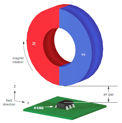
Figure 8: Mechanical Configuration for Case 2
Figure 8 shows the mechanical configuration for Case 2. The radial and tangential magnetic fields versus air gap around the ring magnet are shown in Figure 9 and Figure 10. The radial field component excites the A1262 planar Hall element and is shown as the Z direction. The vertical Hall element responds to the tangential magnetic field; this is displayed as the Y direction. As with the Case 1 ring magnet, the locations of the magnetic peaks of each of the two channels are very consistent relative to the other channel. There is very little variation with air gap. Figure 11 illustrates this more clearly by showing only the results for the minimal and maximal air gaps, 1.5 and 5.0 mm, respectively.
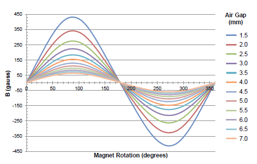
Figure 9: Radial B-Field Diametral Ring Magnet vs. Air Gap
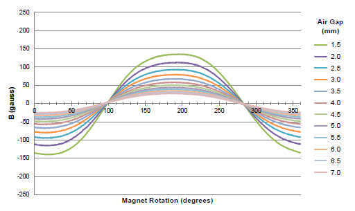
Figure 10: Tangential B-Field Diametral Ring Magnet vs. Air Gap
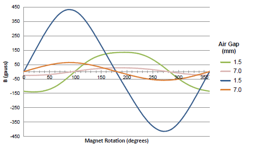
Figure 11: Radial / Tangential B-Field Diametral Ring Magnet vs. Air Gap
Figure 12 and Figure 13 show the magnetic switching behavior of the two sensor outputs with the single pole-pair ring magnet. Given the normal variation in the magnetic switchpoints of the A1262 and a large variation in air gap, the phase relationship of OUTA and OUTB remain very stable.
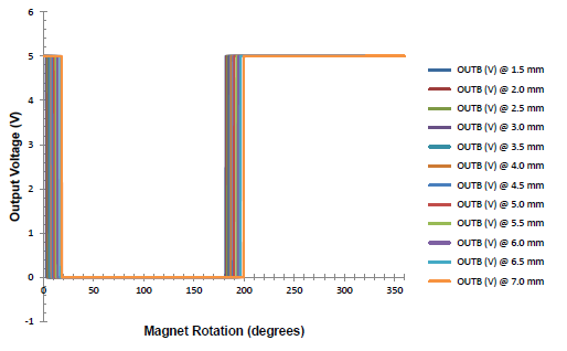
Figure 12: A1262 Multipole Ring Magnet OUTA (radial) vs. Air Gap
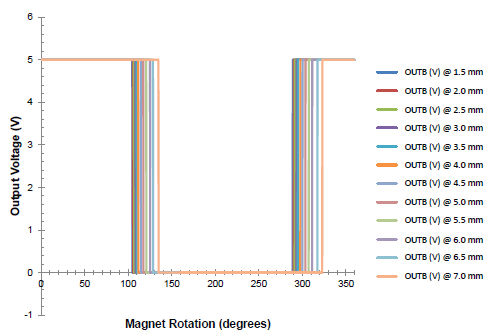
Figure 13: A1262 Multipole Ring Magnet OUTB (tangential) vs. Air Gap
As shown in Table 2 below, both outputs also maintain near-ideal (≈50%) duty cycle independent of air gap.
| Air Gap (mm) |
OUTA Duty Cycle (%) |
OUTB Duty Cycle (%) |
|---|---|---|
| 1.5 | 50.34 | 48.86 |
| 2.0 | 50.34 | 48.72 |
| 2.5 | 50.34 | 48.72 |
| 3.0 | 50.27 | 48.65 |
| 3.5 | 50.07 | 48.65 |
| 4.0 | 50.27 | 48.32 |
| 4.5 | 50.07 | 48.52 |
| 5.0 | 50.27 | 48.32 |
Consistent Duty-Cycle
The data in Table 3 illustrates how little influence air gap and ring magnet pole-pitch have on the OUTA and OUTB signals.
| Ring Magnet | Air Gap | OUTA Duty Cycle (%) |
OUTB Duty Cycle (%) |
|---|---|---|---|
| Case 2 | Min. | 50.34 | 48.86 |
| Max. | 50.27 | 48.32 | |
| Case 1 | Min. | 49.71 | 49.83 |
| Max. | 49.65 | 49.71 | |
| Average Duty Cycle | 49.99 | 49.18 | |
The duty cycle of each signal varies by only a small amount over a 4:1 variation in pole-pitch and a >3:1 variation in air gap. The user is free to choose the ring magnet size based purely on mechanical considerations; the pole-pitch may be almost arbitrarily chosen to yield the desired number of cycles per revolution.
Phase Separation
The phase separation between the OUTA and OUTB signals will vary somewhat with changes in the air gap. This behavior is independent of the ring magnet configuration and is shown in Figure 14 and Figure 15, corresponding to the Case 1 and Case 2 magnets, respectively.
The phase shifts of approximately 4.0° (26.5° – 22.5°) for the multipole Case 1 ring magnet and approximately 12° (102° – 90°) for the single-pole Case 2 ring magnet are caused by the interaction of the internal Hall element spacing, air gap, and magnet dimensions and material.
The magnitude of the total phase shift (Figure 14 and Figure 15) depends on the number of magnetic poles. The larger the number of magnetic poles (smaller pole-pitch) for a given size of ring magnet, the less influence air gap will have on the signal phase.
The phase separation of the OUTA and OUTB signals is generally slightly larger than 90°, because the vertical and planar Hall elements inside the A1262 are not located in exactly the same position on the silicon die.
This signal phase versus air gap relationship means that phase can be used as an indication of system air gap. It could be used, for example, to confirm that the air gap is within the system’s design limits.
This “air-gap signal” can be derived by measuring the time between the falling edges of OUTA and OUTB at a constant speed of magnet rotation. The measured time indicates the air gap distance and will increase if the air gap becomes larger.
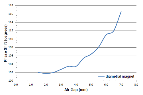
Figure 14: Phase Shift Difference Between Two Falling Edges at the Multipole Ring Magnet Over Air Gap
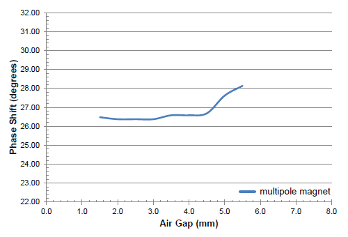
Figure 15: Phase Shift Difference Between Two Falling Edges at the Diametral Magnet Over Air Gap
Observations/Conclusions
As shown above, the A1262’s unique configuration of conventional planar and vertical Hall sensors has the following benefits:
- The A1262 is capable of generating quadrature output signals (≈90° phase difference) where the phase separation is largely independent of the air gap, ring magnet size, or pole spacing.
- The system designer has an unprecedented level of flexibility in selecting the ring magnet and its position and orientation relative to the sensor.
- The user is very likely to be able to choose a standard, off-the-shelf ring magnet, selected to provide the desired number of pulses/revolution.
- The limiting factor at larger air gaps is likely to be the tangential field strength (X or Y in the cases shown here), as the tangential field strength is generally lower than the radial field strength.
- The phase relationship of the OUTA and OUTB signals can be used as an indication of air gap.
Test Circuit
The application circuit used for the case studies above is the typical application circuit shown in the A1262 datasheet and reproduced in Figure 16 below.
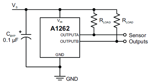
Figure 16: Typical Application Circuit
Ring Magnet Source
The ring magnets used in Case 1 and Case 2 are available from the following vendor, a distributor of Allegro and Sanken Semiconductors:
Matronic GmbH & Co.
Electronic Vertriebs KG
Vor dem Kreuzberg 29
D-72070 Tübingen, GERMANY
Phone: +49 7071 94440
FAX +49 7071 45943
Web: www.matronic.com
Email: info@matronic.de