Applying Harmonic Compensation to the A1335 Output Signal using On-Chip EEPROM and Allegro Applications Software
By Bill Wilkinson,
Allegro MicroSystems, LLC
Introduction
This application note will provide a step-by-step example for configuring harmonic output signal linearization using the A1335 angle sensor integrated circuit (IC). This example will make use of the Allegro A1335 Samples Programmer software, compatible with either the ASEK-20 or ASEK-21 programmer kit. For more advanced, production-level programming, Allegro provides DLLs allowing the functionality displayed in this example to be built into custom-made software and hardware.
Kit Contents and Descriptions
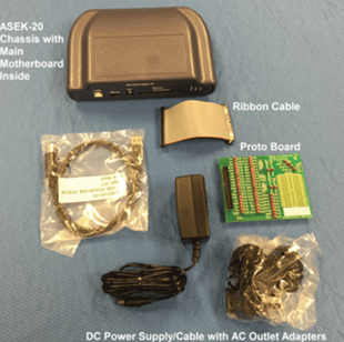
The necessary hardware for A1335 IC evaluation is provided by the ASEK-1335-T-KIT, the contents of which are shown in Figure 1 and Figure 2.
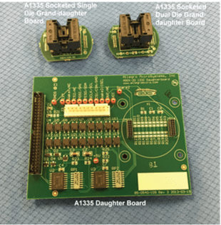
The A1335 daughter board and granddaughter boards provide a simple and convenient way to interface the sensor IC with the ASEK-20 programmer. The spring-action contact pins of the granddaughter board allow solderless testing of sensors. For magnetic evaluations using custom-made hardware, terminals and a Molex connector are provided on the daughter board, allowing connection flexibility.
Connect the hardware as described in the Quick Guide provided in the evaluation kit.
 |
 |
| Figure 1: ASEK-20-T-KIT Contents |
Figure 2: ASEK-1335-SUBKIT-T Contents |
Software
Obtaining the Evaluation GUI
Once the hardware setup is complete, the Allegro software necessary to interface with the ASEK-20 board should be downloaded. This is accomplished by creating an account at the Allegro Software Registration Portal (https://registration.allegromicro.com/login) and registering for the A1335 IC.
Once registered, the A1335 evaluation GUI software may be downloaded from the Dashboard.

(https://registration.allegromicro.com)
Setting up the Software
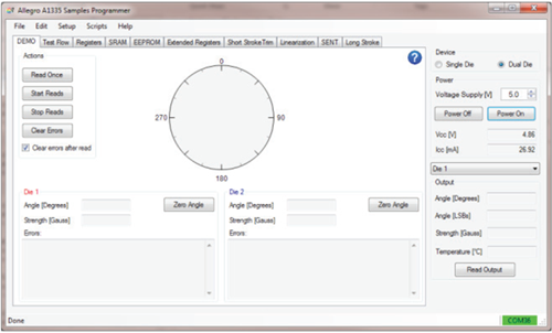
After downloading and extracting the Allegro software, doubleclick on the Allegro A1335 Samples Programmer executable. This will bring up the samples graphical user interface (GUI), with the DEMO tab selected. This tab will display the sensor angle, any locked-in errors (such as a power-on reset, or low magnetic field flag), and the applied magnetic field strength incident on the sensor. However, prior to communicating with the sensor, the COM Port and protocol must be selected and the
device must be powered on.
To select the proper COM port and communication protocol, click on the “Setup” menu in the upper left, and select “Communication…” This will bring up the “Communication Setup” window.
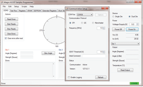
Select the COM port corresponding to the ASEK-20 programmer. If the COM port number is not known, observe the available COM ports listed in the pulldown menu, unplug the ASEK-20 USB cable from the computer, and hit the Refresh button—the listing that disappears corresponds to the ASEK-20 COM port. Likewise the COM port listing which appears after the ASEK-20 is plugged in is the correct address.
If the COM port is correct, the Status box in the bottom will update to “Active” and report the ASEK-20 software version (in this case, version 127.6.3.1). Select the desired communication protocol and frequency, and exit the window. When selecting the frequency, consider the resistive and capacitive loads that may have been added to the communications pins of the IC. External filtering / load circuits (including long wires) can degrade the communications signals and cause communication issues.
Click the “Power On” button. The A1335 should now be powered up with the voltage (5 V above) and curren (26.92 mA above) shown on the rightmost panel.
Magnet Setup
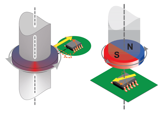
Align the sensor as desired with a target magnet. As described in the “Advanced On-Chip Linearization” application note, the recommended field strength should be between 300 and 1000 G; however, small deviations below 300 G will not significantly impact performance. Although harmonic linearization was developed to allow high-accuracy off-axis performance, it may also be used to minimize the nonlinearities resulting from mechanical misalignment errors present in more conventional on-axis applications.
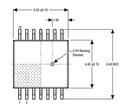
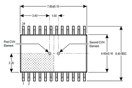
It is important to be aware that the CVH sensing element is not centered within the A1335 (both the single- and dual-die versions) package. For instance, when mounting the single-die sensor in an off-axis application (leftmost illustration in Figure 6), the pin 1 side of the sensor IC should be facing away from the magnet. This allows the CVH to be as close as possible to the target magnet.
Raw Data Recording
With the A1335 properly aligned with the target magnet, the raw (or pre-linearization) performance may now be measured. By clicking on the “Linearization” tab, the type of compensation can be selected via a pulldown menu (either Harmonic or Segmented). In general, Harmonic linearization better compensates for sinusoidal error resulting from eccentricity in sensor mounting, and will be the method shown in this example.
Number of Sample Points
To quantify the harmonic error superimposed on the sensor’s transfer function, the output for a complete magnet rotation must be measured. The number of measurement points taken throughout this rotation can be selected via the text box in the upper-left corner of the Linearization tab. The minimum number of points which may be used is eight; however, it is recommended at least 16 samples be taken—this allows the 7th order harmonic to be resolved. Historically, harmonics 1, 2, and 4 are the major contributors to the final error. Any number of samples up to 2048 may be used; however, if the number is not a power of two (16, 32, 64, etc.), the collected data will be interpolated to obtain a power-of-two length array, prior to performing the FFT. This is performed automatically within the GUI, once the “Calculate” button is pushed.
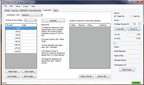
When using the Allegro A1335 Samples Programmer GUI, it is assumed each of the sample points is evenly spaced throughout the magnet rotation. To aid in data taking, the expected encoder position for each of the sample points is shown in the left column of the leftmost table. Unevenly spaced data may also be used for
linearization; however, this requires additional software postprocessing, and must be loaded in as a text or CSV file. For more details on the format required, see the “Programming Harmonic Linearization” application note.
Recording Data
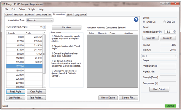
To begin sampling raw angle data, position the magnet to the desired starting position; this does not need to (and often will not) correspond to the sensor IC’s zero position. Once positioned, ensure the data-entry row corresponding to “Encoder 0.000” is highlighted in blue (as shown in Figure 9); if it is not selected, then select this row using the mouse. Click the “Read Angle” button to poll the sensor IC’s output at this magnetic position.
The angle value will be placed adjacent to the corresponding encoder value. The next encoder positon row will now be highlighted in blue. Move the magnet to this position and click “Read Angle”. Repeat this until a complete rotation has been accomplished, and all rows are full.
The data can be saved by using the “Save Angles…” button. This allows the raw data to be loaded at a later time (using the “Load Angles…” button), without retaking the angle measurements.
Calculating and Selecting Harmonic Components
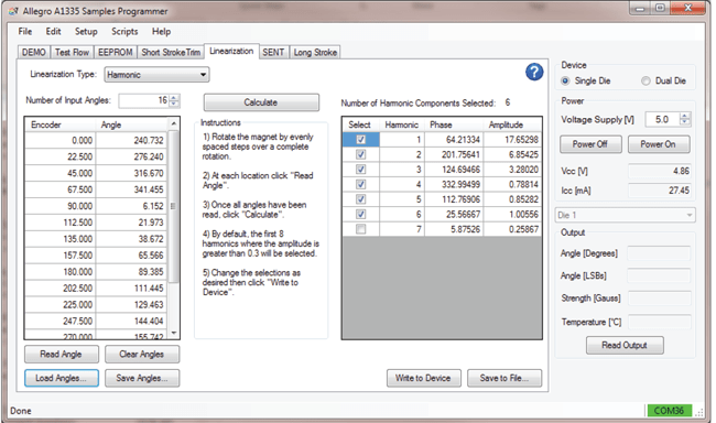
Once all samples have been taken (and entered using the “Read Angles…” button), the harmonic error components are calculated by clicking on the “Calculate” button. The amplitude (in degrees) and phase for all observable harmonics are displayed in the rightmost table. The harmonics for which compensation is applied are selected via the check boxes in the leftmost column; by default the first eight harmonic components with an amplitude greater than 0.3° are selected. Be aware when selecting a greater number of harmonics that the test (EEPROM programming) time of the IC will increase. Optimization of output accuracy versus the number of harmonics chosen should be conducted by the user, and varies by application.
By clicking on the column headers, the table may be sorted in ascending or descending order. This allows the largest error contributors to be easily identified.
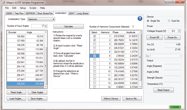
The A1335 is capable of compensating for up to 11 different harmonic components (however, beyond eight harmonics, shortstroke features become disabled). In the case where 17 or more samples are taken, there will be a larger number of selectable harmonic components than registers. To provide compensation for higher harmonic orders, up to 3 consecutive harmonics may be skipped, i.e. harmonic orders 1, 2, and 6 may be selected, omitting 3, 4, and 5. This is shown in Figure 12.
Programming the A1335
The selected harmonic coefficients are programmed into EEPROM by pressing the “Write to Device” button. This button unlocks the sensor, enters idle mode, transfers the harmonic coefficients to memory, pulses VCC to write EEPROM, and powercycles the sensor such that EEPROM is properly loaded into SRAM.
When prototyping, it is often easier to experiment using volatile memory rather than nonvolatile EEPROM, where potential missteps are more impactful and harder to correct. In these cases, power-cycling the sensor following harmonic linearization is not desired, as it removes any configurations made in volatile memory. To prevent this, if the CTRL button is held down when clicking on the “Write to Device” button, no power cycle is performed. Instead, the selected coefficients are written to both
EEPROM and SRAM. By writing the values to SRAM, the coefficients have immediate impact, without the need for a power cycle.
Verifying Compensation
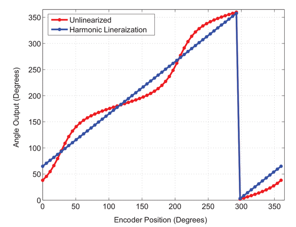
After the programmed EEPROM coefficients are loaded into SRAM, the sensor will begin applying harmonic compensation. This compensation may be verified by rotating the target magnet through a complete rotation and observing the output behavior. The output should now increase linearly from a given starting position through 360 and back to the initial position. This is shown in Figure 13.
Setting the Zero Position (Zero-Angle Position)
Following end-of-line linearization, it is now possible to make final adjustments to the zero-angle position, as reported by the sensor. To perform this, move the target magnet to the desired zero-angle position, then in the Demo tab of the A1335 GUI, click the “Zero Angle” button. This records the current angle, and writes it into the ZERO_OFFSET field within EEPROM (0x306, bits 11:0). This value is subtracted from the compensated angle value at the end of the signal path, thus the value stored in the register becomes the position resulting in a 0° output. Since the subtraction is performed after compensation within the digital signal path, this value must be set following the completion of harmonic (or segmented) linearization.0 50 100 150 200 250 300 350
Frequently Asked Questions and Common Issues
Using Harmonic Linearization only made the performance worse. What happened?
This is most likely due to a phase offset within the harmonic coefficients, thus the correction no longer properly aligns with the error components and in some cases may amplify the error instead of removing it. The most common way this occurs is when the ZERO_OFFSET field in EEPROM (0x306, bits 11:0) is set, prior to taking the raw data used for calculating the coefficients.
This should only be an issue when not using the provided A1335 GUI to record data, as the GUI sets the corresponding ZERO_OFFSET field within SRAM (0x06, bits 15:0, left aligned) to zero.
If a large post-linearization angle error is encountered and data was recorded outside of the GUI environment (Allegro DLLs, or a third-party sampling scheme), ensure the ZERO_OFFSET field is reset to 0, and retake the raw angle data.
Issues programming the zero angle positon following linearization.
This is most likely due to a pre-existing value in the ZERO_OFFSET field within EEPROM.
As mentioned above (see Setting the Zero Position section), the value within the ZERO_OFFSET field is subtracted from the compensated angle just prior to being output by the sensor (see Figure 14). Thus if the zero position was programmed before completing harmonic linearization, the value is no longer correct (notice the first point changed, post linearization, in Figure 13), and the desired zero position is incorrect.
To correct this, reset the ZERO_OFFSET field to zero. This can be done from the “EEPROM” tab within the GUI. Then, after moving the target magnet to the desired zero position, click the “Zero Angle” button on the “Demo” tab to program the correct value.
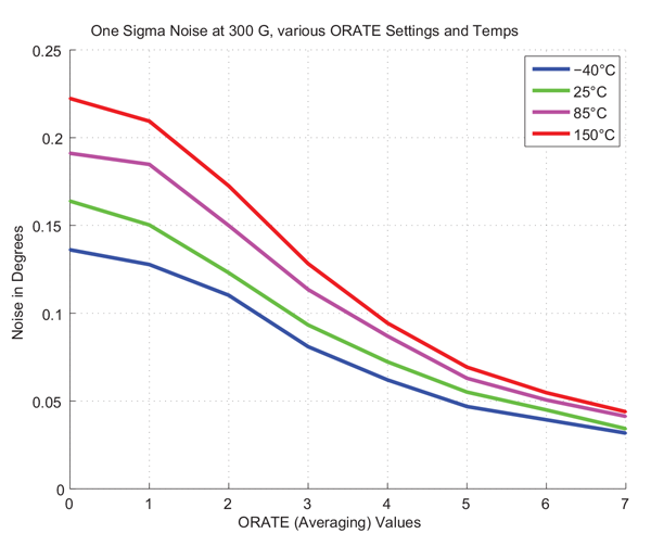
Encountering high noise during off-axis operation.
Noise is highly dependent on the magnitude of the magnetic field. Nominally, the A1335 will present approximately ±0.17° of variability in the measured angle value, at 900 G and room temperature. Due to the large swings in field strength inherent with off-axis mounting, it is likely that portions of the magnetic rotation will present greater noise than others; in other words, because of the variability of the magnetic field magnitude over positon, the noise level may become position-dependent.
To mitigate these effects, it is important to maximize the field strength the sensor observes, as this will establish a lower baseline noise level. This can be accomplished by ensuring the target magnet is of sufficient strength (i.e. 300 G or greater as measured by the sensor) and minimizing the air gap between the
CVH element and magnet. In addition to magnet-related parameters, the A1335 may be configured to accumulate and average multiple transducer outputs, increasing the effective resolution of the system at the cost of a slower refresh rate. The number of samples used in the average is configured using the ORATE field within EEPROM (0x308, bits 23:21). See the A1335 programming manual for more details on ORATE settings.
Harmonic linearization did not sufficiently improve sensor accuracy.
Harmonic compensation has the ability to significantly improve accuracy, reducing errors upwards of ±40° to less than 1°. The improvement will depend on the number of harmonics applied, which are determined by the number of raw samples taken. Allegro recommends using a minimum of 16 samples, allowing up to the 7th harmonic error to be calculated. If, following compensation, the resulting accuracy is not sufficient, it is possible higher order harmonics are contributing to the error. A larger number of initial samples should be taken; in this case, a sample size of 64 is recommended; beyond this little benefit is derived.
The information contained in this document does not constitute any representation, warranty, assurance, guaranty, or inducement by Allegro to the customer with respect to the subject matter of this document. The information being provided does not guarantee that a process based on this information will be reliable, or that Allegro has explored all of the possible failure modes. It is the customer’s responsibility to do sufficient qualification testing of the final product to insure that it is reliable and meets all design requirements.