Using ASEK Programmers with Long Harnesses and Capacitive Loads
By Wade Bussing,
Allegro MicroSystems, LLC
Introduction
Allegro’s ASEK programming kits allow users to easily interface, program, and evaluate Allegro sensor ICs to suit the needs of many applications. Allegro’s programmers are intended to work in conjunction with device-specific daughterboards. However, they are often used to interface with test benches and custom modules. The link between Allegro programmers and these modules may be a non-ideal setup consisting of long test leads and external components that can impact the quality of the transmitted signals. These degraded signals may hinder the programmer’s ability to reliably communicate with the Allegro sensor IC. Allegro’s A1341 high-precision linear sensor IC was used as the test IC for this report, but the concepts and techniques apply to a number of Allegro sensor IC families that follow a similar communication protocol.
Test Setup
For the purpose of these tests, long leads (3 feet long), an interface box, and a custom device fixture (with 2 feet of wiring) were used to create a potentially non-ideal test setup. These conditions are similar to those that might be found in a laboratory environment. The block diagram in Figure 1 shows the connections used to interface the Allegro sensor IC with the ASEK Programmer.
An ASEK-05 was used for this evaluation; however, these same debugging techniques apply to Allegro’s ASEK-20 Programmer (a newer generation programmer).
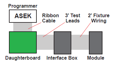
Figure 1: Test Schematic
In addition to long leads and fixtures, there can also be a number of components external to the sensor that affect the condition of transmitted signals. For example, the A1341 requires a pullup resistor on the output for PWM and SENT operation (supplied here by the ASEK Programmer). For the tests documented below, either a 10 or 100 nF bypass capacitor was connected between the VCC and GND pins of the A1341.
Software and the ASEK Programmer
Allegro has developed device-specific software to work with the ASEK programmers. This software can be found on the Allegro MicroSystems Software Portal, (https://registration.allegromicro.com).
For these tests, the A1341 Samples Programmer was used to control the ASEK-05 Programmer. The settings used with the A1341 Samples Programmer and the ASEK-05 are shown below in Figure 2.
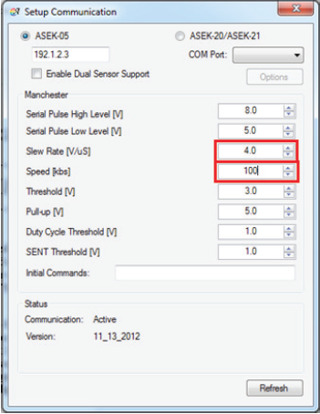
Figure 2: Settings for 100 kbps with ASEK-05
Typical Capacitive Loads
Under small capacitive loads (1 to 10 nF), the ASEK-05 can communicate with devices via Manchester at up to 100 kbps, even over long harness lengths. The oscilloscope plot in Figure 3 below shows a successful Manchester message over the long wire harness.
Notice that the serial-high level goes exactly to 8 V, and the serial-low pulse never dips below 5 V. These are the desired levels for Allegro’s A1341 linear sensor IC. Serial-high and serial-low level specifications may vary between device families. Reference the datasheet for each particular device.
Figure 4 shows how, at 100 kbps, the Manchester message degrades over a long harness with the use of 100 nF bypass capacitor.
A message in this form can periodically be interpreted by the device, but it is unreliable. The ringing is not desired, and the serial-low level may dip enough to momentarily turn off the device.
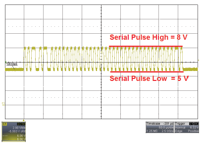
Figure 3: 100 kpbs Manchester with ASEK-05 and 10 nF bypass capacitor
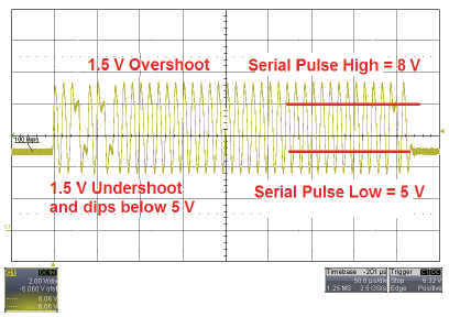
Figure 4: Degraded Manchester sequence over long harness and 100 nF bypass capacitor at 100 kbps
ASEK Settings
This section will summarize some of the settings available in the A1341 Samples Programmer. The goal is to tune Manchester communication so that it may be read correctly by the Allegro device, even over a long harness with large capacitance.
One parameter that can be changed is the Manchester communication speed. For the long wire and 100 nF capacitor condition, the Manchester communication speed was slowed to 40 kbps.
The oscilloscope plot in Figure 5 shows the resulting waveform. The serial pulses settle at the correct levels for the A1341, but some peaking still persists. Another parameter that can be changed is the slew rate of the ASEK-05.
The slew rate was reduced from 4 V/μs to 0.8 V/μs, significantly reducing peaking, as shown in Figure 6.
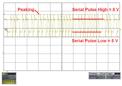
Figure 5: Manchester from ASEK-05 at 40 kbps with 100 nF bypass capacitor and long harness
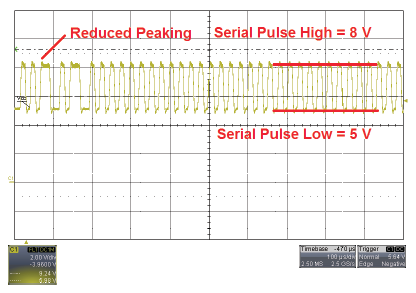
Figure 6: Successful Manchester message from ASEK-05 to device at 40 kbps and slowed slew rate with 100 nF bypass capacitor
Reading Responses from the Device
The message sent by the ASEK programmer is only one side of the programming equation. The following section will outline steps to improve reading messages that are returned by the Allegro sensor IC back to the ASEK Programmer.
For reference, a successful Manchester response from the A1341 is shown in Figure 7.
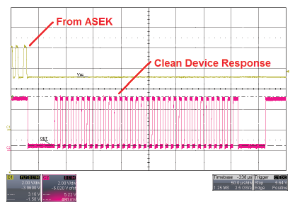
Figure 7: A1341 responding via Manchester to a read request
The scope plot in Figure 8 shows how adding a load capacitor affects the response returned by the device. The light pink channel shows A1341 sensor IC’s response with a 1 nF load capacitor, while the dark red channel shows the response with a 10 nF load capacitor. These stacked plots clearly illustrate how the load capacitor impacts the device’s response.
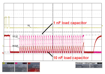
Figure 8: A1341 responding via Manchester to a read request
The device’s response with a 1 nF load was not ideal, but was read correctly by the ASEK programmer.
To improve the waveform under the 10 nF load condition, the communication speed was slowed down to 15 kbps under the Communications setup panel. This allowed the loaded output to return to an appropriate level. Still, the waveform was not ideal, but this can be correctly interpreted by the ASEK Programmer.
The threshold at which the ASEK compares the Manchester message was then lowered. “Threshold” was changed from 3 V to 2 V. The ASEK settings and resulting waveforms can be seen in Figure 9 and Figure 10.
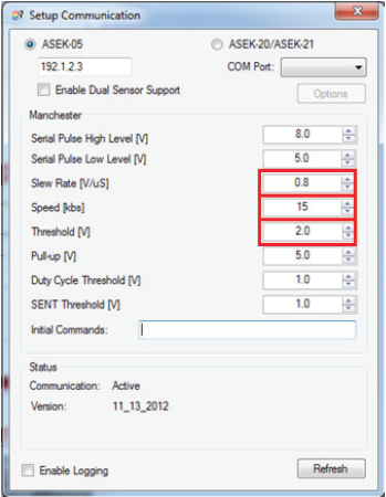
Figure 9: ASEK settings used for A1341 with a 10 nF load capacitor
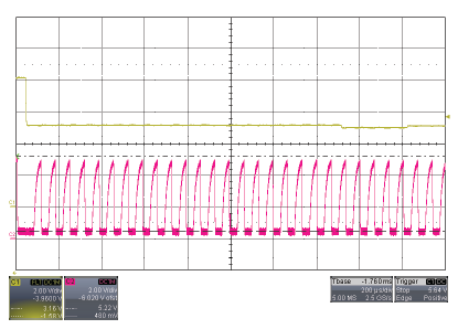
Figure 10: A1341 device’s response to read request with 10 nF load capacitor
ASEK-20
Some device families are supported by both the ASEK-05 and ASEK-20 programmers. The ASEK-20 was designed to be a flexible programming system to support multiple device families and protocols including I2C, SPI, and Manchester. Many of the settings are identical between ASEK-05 and ASEK-20, but the ASEK-20 Manchester speed is capped at a lower rate.
Conclusion
Allegro’s ASEK programmers were designed to support multiple device families and digital communication protocols; however, external connections and device loads may impact the probability of successful programming. The default settings of the ASEK programmers will not always work to communicate with a device. The correct combinations of communication speed, slew rate and pulse levels can all vary under different conditions.
Certain options may be specific to a particular device, and settings that work well for one family may not work with another.
The techniques outlined in this document are general practices for increasing the reliability of communication between Allegro’s sensor ICs and the ASEK programmer under non-ideal conditions.
All testing was conducted using Allegro Samples Programmer for the A1341 high-precision linear Hall-effect sensor IC. Visit Allegro Microsystem’s software portal (https://registration.allegromicro.com) to download the correct programming software for your Allegro sensor IC.