Have Questions? Let us help!
We're passionate about innovation. Reach out and you'll hear back from an expert shortly.
One of our solution experts will be in touch with you shortly. Keep reading to learn more about our industry leading solutions.
Download PDF version
By Shaun Milano, Allegro MicroSystems, LLC
Allegro® MicroSystems has introduced innovative devices designed for use in motor or inverter control applications. This application note discusses the features of the Allegro ACS716, designed as a 3.3 V supply device, and compares it with the ACS710, 5 V device that can be integrated for output into 3.3 V systems.
Allegro has released a new current sensor for motor inverter applications that improves operation when used with commonly available 3.3 V A-to-D converters. The Allegro ACS716 current sensor IC provides an economical and precise means for current sensing applications in industrial, commercial, and communications systems. The device is offered in a small footprint surface mount SOIC16 package that allows easy implementation in customer applications because it is fully integrated. Current flows in and out of the package on one side and the signal leads provide an analog output and fault function and filtering on the other side of the package (see figure 1).This configuration provides a low resistance conductor of only 1 mΩ and provides high voltage isolation. The device is similar to the ACS710 but programmed and tested at 3.3 V.
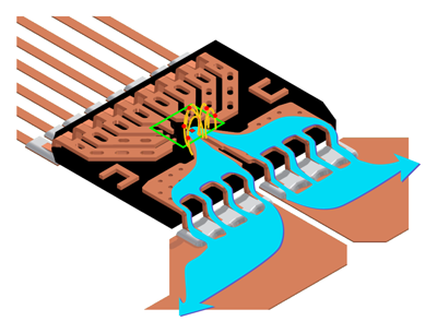
Figure 1. Primary sensed current flow
The ACS710 device is optimized at the Allegro factory for operation with 5 V supply voltage, and the analog output voltage can swing to greater than 4.5 V when measuring full scale current. Using a 3.3 V A-to-D converter with this device requires a resistor divider to accommodate the input range of the converter (figure 2). Dividing down the analog signal is common in such applications, but it does have an influence on overall system accuracy. There is also a slight cost to the system for the resistors and for picking and placing the resistors on a PC board.
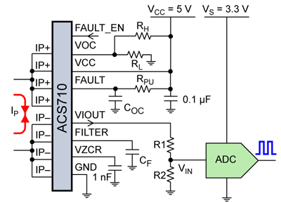
Figure 2. ACS710 with 3.3 V A-to-D converter
The VIN to the converter in figure 2 is resistor-divided by R1 and R2:
VIN = VIOUT × R2 / (R1 + R2).
If using 1% resistors, the error can be just under 2% worst case, due to mismatch in the resistors.
The ACS716 (figure 3) is a newer product offering from Allegro that is optimized at 3.3 V. This provides an output voltage at full scale of 3 V that can go directly into the A-to-D converter, which eliminates the requirement for a resistor divider network.
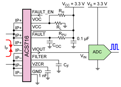
Figure 3. ACS716 with 3.3 V A-to-D converter
For a useful article on the operation of the ACS710 device, which is also applicable to the ACS716 device please see AN296088, Improving Efficiency in Smart Grid Applications with Fully Integrated Current Sensing ICs.
The datasheets for both devices can be found on the Allegro website, under current sensors.