Hall Sensors for Fuel Level Sensing
Fuel Level Sensor Using Hall-Effect Sensor ICs - Allegro MicroSystems
By Shashank Wekhande and Ranjit Farakate,
AvantGarde Solutions Pvt. Ltd.,
Consultant to Allegro MicroSystems, LLC
Abstract
Hall-based fuel level sensor ICs are developed to provide high reliability and accurate fuel level sensing for automotive applications. The application of linear and angle sensor ICs for coil-based and digital cluster indicators is presented in this applications note.
Introduction
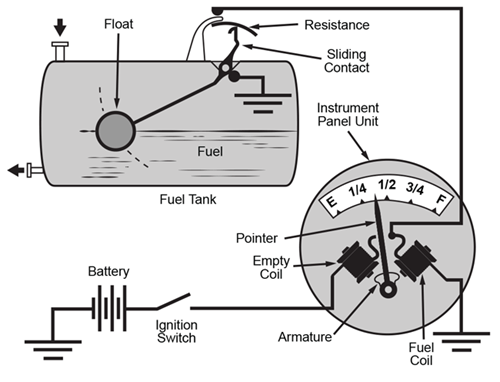
A fuel level sensor (FLS) is used in all automobiles to indicate fuel level. Various methods are used to measure fuel level such as resistive film, discrete resistors, capacitive, and ultrasonic. Resistive-based sensors are most commonly used for this application. These sensors are mechanically connected to a float which moves up or down depending on the fuel level. As the float moves, the resistance of the sensor changes. This sensor is part of a current balance circuit of the fuel gauge display circuit which typically consists of coils for actuation of the display needle. As the resistance of the fuel sensor changes, the position of the needle changes proportional to the current flowing in the coil. A typical resistor-based FLS is shown in Figure 1.
The disadvantage of the resistive contact-based sensor is the wear and tear of the sensor due to the sliding contact inside the sensor elements. The wear and tear leads to a reduction in the sensor life.
This paper describes methods to use Hall-based sensor ICs for non-contact sensing for FLS applications.
Non-Contact Hall-Sensor-Based FLS
Hall sensor ICs typically sense the magnetic field passing through the IC. For a fuel sensing application, a diametric magnet must be installed such that its rotary movement is proportional to the float movement. Also the sensor needs to be installed in close proximity to the magnet. This is simpler to adopt for retrofitting compared to other non-contact sensor technologies. The magnet could be sealed to protect it from degradation inside the fuel. Even if the fuel is contaminated, the sensing operation will not be affected.
Hall Sensor IC Options for FLS
Allegro offers various options for FLS applications to suit accuracy, linearity, output interface, and cost.
- Linear Hall-Effect Sensor
Linear Hall-effect sensor ICs have an output signal that is proportional to absolute magnetic field. The IC output voltage changes based on magnetic field.
- PWM Output: PWM output offers advantages such as better noise immunity. These type of sensors are suitable for cross-coil-based clusters.
- Analog Voltage: In digital clusters, often a microcontroller is used to interface with the LCD and sensor output. An analog input voltage from the sensor is given to the ADC input of the microcontroller. These ICs operate from either a 3.3 V or a 5 V supply and ratiometric to the supply.
Two-point programming offers compensation for magnet and air gap variation. Allegro also offers multipoint programming to adapt to non-uniform tank geometry.
- Angle Hall Sensor
Angle sensors are based on measurement of the absolute angle of the magnetic field. This eliminates error due to magnet and air gap variation.
- PWM Output: PWM output ICs offer advantages such as better noise immunity and direct connection to the vehicle battery.
- Analog Voltage: IC provides analog output voltage proportional to angle.
- PWM Output: PWM output ICs offer advantages such as better noise immunity and direct connection to the vehicle battery.
Table 1: Sensor Offerings by Allegro MicroSystems for Fuel Sensing Purpose
| Sensor | Output | Technology | Programmability | Accuracy | Cost |
| A1356 | PWM | Linear Hall | Sensitivity + QVO Offset | Better | Low |
| A1377 | Analog Voltage | Linear Hall | Sensitivity + QVO Offset | Better | Medium |
| A1330 | Analog + PWM | Angular Hall (CVH) | Gain + Short Stroke + Zero Offset + Clamp + Averaging + Rotation | Best | Low |
| A1338 | PWM | Angular Hall (CVH) | Zero Offset + Averaging + Rotation | Best | High |
Fuel Tank Construction
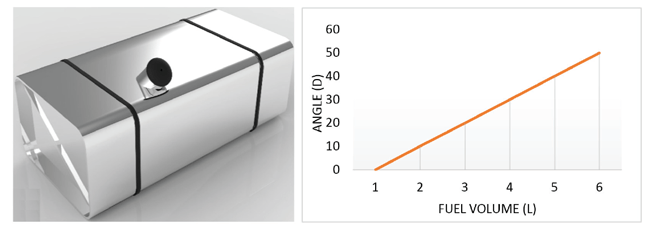
Fuel tank construction varies from automotive model to model. Some tanks with regular geometry result in a linear volume to float angle. For such tanks, only two-point programming would suffice. An example of a uniform fuel tank and its characteristics are shown in Figure 2.
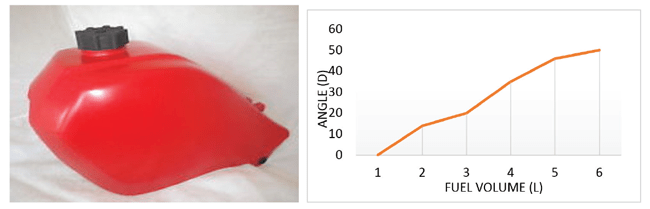
However, a majority of the fuel tanks are non-uniform in terms of
volume to float angle. A typical non-uniform tank and its characteristics
are shown in Figure 3. For these type of tanks, multipoint
programming in the IC is required for output signal linearization.
Linear PWM Hall Sensor for Analog FLS with Coil-Based Cluster
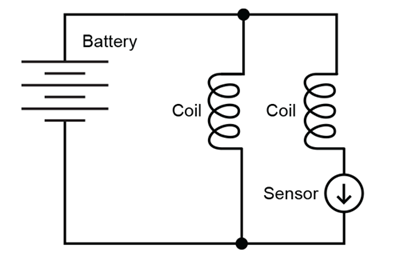
This is the most commonly used FSU for low-cost applications. The cross-coil arrangement is shown in Figure 4. One side of the coil is directly connected across the battery and the other side is connected to battery with a series sensor connection. The coil resets to its normal position when currents in both coils are the same. The needle deflects from normal position when sensor current varies. This arrangement offers cancellation for battery voltage variation. Sensor current to needle angle is not linear due to thermal effects.
The A1356 IC offers a system-level ratiometric (output which adjusts according to the supply voltage) output solution with minimal components. The A1356 works with internal reverse battery protection. This IC offers two-point magnetic field programming to adjust offset and sensitivity. This allows 4 to 18 V to compensate for magnet, coil, and manufacturing air gap tolerances.
An application circuit for an A1356-based FSU is shown in Figure 5.
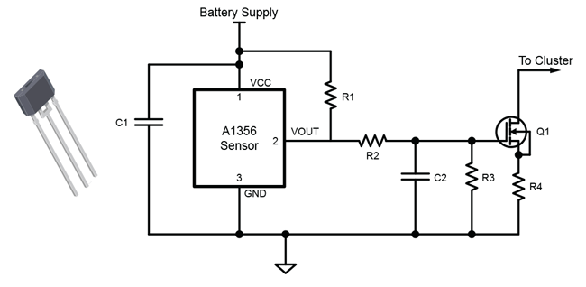
The RC filter of R2 and C2 converts PWM output of the A1356 to a proportional analog voltage. MOSFET Q1 converts this voltage to a current output suitable to drive the coil.
Magnet selection is not very critical for this application. NdFeB or ferrite magnets are suitable for this application. For better repeatability, magnets with tighter tolerances should be used.
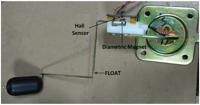
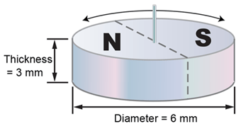
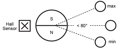
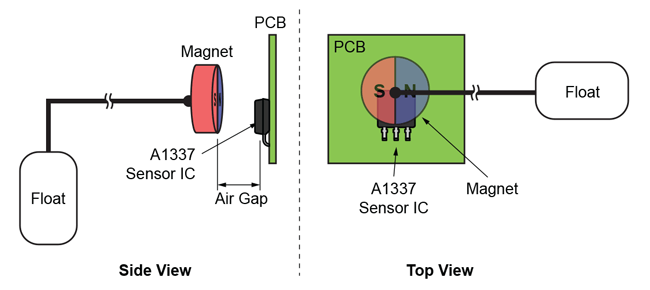
The magnet used for this application is a diametric type of magnet (round) shown in Figure 7 and it is fitted on the pivot of the float and the sensor is placed on the magnet surface with 2 mm of air gap, as shown in Figure 6. Magnet orientation and linear Hall sensor positioning are shown in Figure 8.
EXPERIMENTAL RESULTS
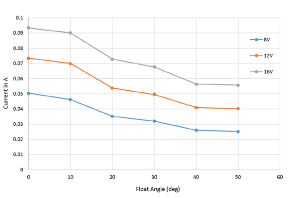
Figure 9 shows linear coil current with respect to float angle. Coil current changes with supply voltage and is inherently non-linear due to self-heating thermal effects.
Linear Analog Hall-Effect Sensor for Digital FLS with Microcontroller-Based Cluster
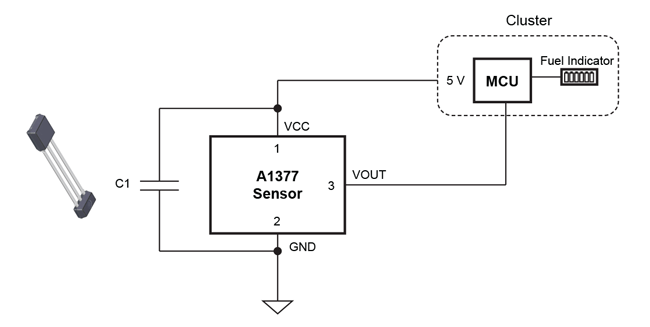
The A1377 is a programmable linear Hall-effect sensor which provides an analog output voltage proportional to magnetic field. The A1377 provides a ratiometric output between 4.5 and 5.5 V input supply voltage. Use the 5 V supply from the cluster used by the interfacing ADC to power the A1377. A linear analog Halleffect sensor-based digital FLS is shown in Figure 10.
The A1377 provides two-point magnetic field programming to adjust offset and sensitivity. This allows users to compensate for magnet, coil, and manufacturing air gap tolerances.
EXPERIMENTAL RESULTS
Figure 11 shows linear output voltage with respect to float angle.Output voltage is linear over 50 degrees of float angle displacement.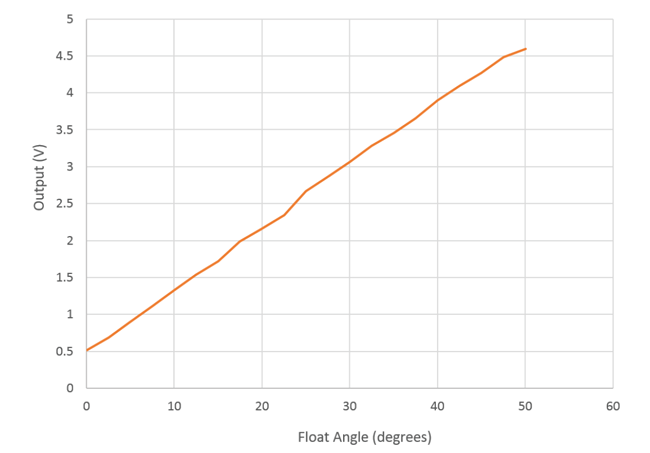
Figure 12 shows the A1377 linear sensor and magnet placement on the fuel sensor assembly.
Angle Hall Sensor for Digital FLS with Microcontroller-Based Cluster
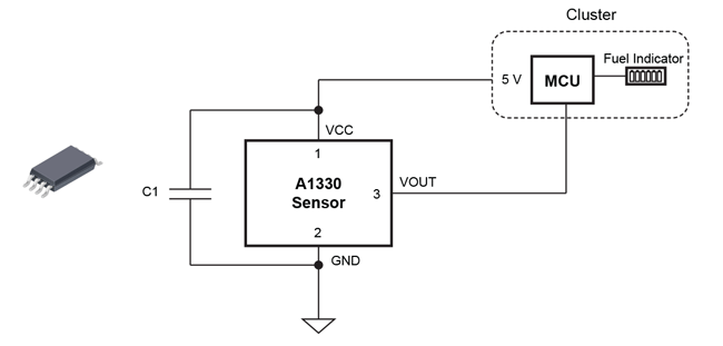
Linear sensors suffer from errors due to air gap or magnet drifts. Linear angle sensors are also suitable up to 60 degrees angular displacement. Angle sensors provide wide angular displacement measurement with output voltage independent of air gap and absolute magnetic field. The A1330 is a 360° angle sensor IC that provides contactless angular position based on magnetic circular vertical Hall (CVH) technology. An angle Hall sensor-based digital FLS is shown in Figure 13. This application uses a diametric magnet.
Programmable parameters include zero offset to provide flexible magnet placement and short angular displacement for full dynamic range.
EXPERIMENTAL RESULTS
A1330 output voltage with float angle is shown in Figure 14 with 6 mm × 3 mm diametric magnet. Results show a linear output voltage over 75 degrees of displacement which is independent of air gap.
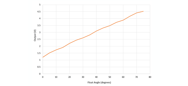
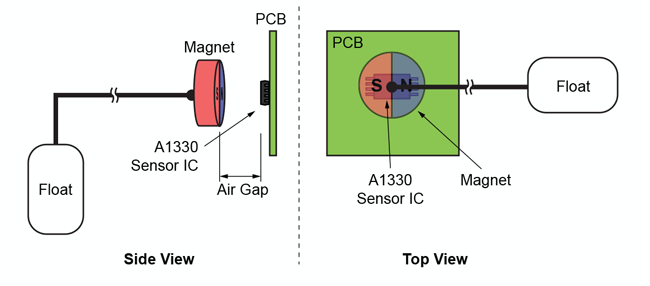
Figure 15 shows the A1330 angle sensor IC and magnet placement on the fuel sensor assembly.
For battery operated FLS, use the non-ratiometric version of A1330 and provide local LDO in fuel sensor assembly.
A PWM output version of A1330 can be used for digital FLS for better noise immunity.
Table 2: Comparison of Various Programmable Hall Sensor Options
| Sensor | Application | Pros | Cons |
| A1356 Linear Sensor (PWM) |
Coil-Based Analog FLS |
Better noise immunity, ratiometric output with battery voltage, offset and sensitivity programming compensate magnet and air gap tolerances during manufacturing. |
Magnet orientation is critical during assembly. Output error with magnetic field drift. |
| A1377 Linear Sensor (Analog) |
Digital FLS | Offset and sensitivity programming compensate magnet and air gap tolerances during manufacturing. |
Magnet orientation is critical during assembly, Output error with magnetic field drift. Needs 5 V supply. |
| A1330 Angle Sensor (Analog + Ratiometric) |
Digital FLS | Output voltage independent of air gap and absolute magnetic field, flexible magnet placement, short angular displacement for full dynamic range, SMD package. |
Need 5 V from cluster. |
| A1330 Angle Sensor (Analog + Non- Ratiometric) |
Analog FLS | Output voltage independent of air gap and absolute magnetic field, Flexible magnet placement, short angular displacement for full dynamic range, SMD package. |
Needs LDO for 5 V supply. |
| A1330 Angle Sensor (PWM) |
Digital FLS | Output voltage independent of air gap and absolute magnetic field. Flexible magnet placement, short angular displacement for full dynamic range, better noise immunity, SMD package. |
Needs 5 V supply from cluster or LDO. |
Conclusion
Hall-based fuel level sensing offers reliable non-contact fuel measurement for automotive applications. Allegro offers a wide range of Hall sensors suitable for different FLS systems. All the sensors use simple diametric magnet and offers programming to achieve a linear output signal, even with asymmetric fuel tank shapes.
Copyright ©2017, Allegro MicroSystems, LLC
The information contained in this document does not constitute any representation, warranty, assurance, guaranty, or inducement by Allegro to the
customer with respect to the subject matter of this document. The information being provided does not guarantee that a process based on this information
will be reliable, or that Allegro has explored all of the possible failure modes. It is the customer’s responsibility to do sufficient qualification
testing of the final product to insure that it is reliable and meets all design requirements.