Vehicle Safety Systems
By Christine Graham, Systems Engineer
Seat Position Sensing
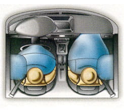
Figure 1. Front- and side-impact air bags require precise data on the location of the seats and occupants.
Occupant safety is one of the most critical elements of the automobile design. As a result, safety systems continue to become more sophisticated in order to limit, and ultimately prevent, personal injury in the case of an accident.
Seat position sensing is used in safety systems to determine the position of an occupant in relation to the steering wheel, preventing the air bags from deploying with excessive force.
The most common solution today incorporates two-wire, unipolar, Hall-effect switches in sensing discrete seat position zones. The sensor IC must relay this information in the form of a digital output to the controller unit indicating a particular zone. This information must be correct at start up of the vehicle, so the sensor IC output must decode without any user action.
The seat track is typically a ferrous metal material capable of interrupting the magnetic field between the Hall-effect sensor IC and a magnet. The ferrous metal of the seat track passes between the switch and the magnet causing the switch to turn on or off, relaying seat position information to the controller unit. A change in the output state of the sensor IC indicates to the controller unit that the seat has passed into a particular zone.
There can be any number of zones depending on how many Hall-effect sensor ICs are used, assuming two sensor ICs per seat track, four zones would be possible. The information, provided by the Hall sensor IC, is processed by the controller to determine the seat position relative to the steering wheel. A seat that is in one of the closer zones to the steering wheel would indicate to the controller unit that a lower force deployment is necessary. Seat positions that are in one of the rear zones, furthest from the steering wheel, require a higher force deployment. The controller unit decodes the output states of the Hall-effect sensor ICs to determine in which zone the seat is positioned. Two sensor ICs will provide a convenient Grey Code output as shown in figure 2 and the table below.
Figure 2. Position sensor ICs relay proper seat location to the controller unit the entire time the vehicle is on. Occupants are unaware of the fact that the vehicle is making life or death decisions automatically with no user interface required.
| Zone | Hall 2 Output | Hall 1 Output |
| 1 | 0 | 0 |
| 2 | 0 | 1 |
| 3 | 1 | 1 |
| 4 | 1 | 0 |
The vast selection of Hall-effect sensor ICs allows different solutions for the same application. A higher resolution may be required to determine exactly where the seat is at all times. The highest resolution solution is to use a linear, analog Hall sensor IC, which produces a voltage output proportional to the strength of the magnetic field. A dual pole magnet in a slide-by configuration with the linear will produce an output ranging from 0 volts to 5 volts with the proper design.
Hall-effect technology is highly reliable and relatively inexpensive. If automatic sensing is required the solution must be dependable.
If higher precision is required, programmable switches and linear devices are available, and can minimize stack up tolerances by allowing end-of-line programming.
Ferrous targets can be detected using a back-biased Hall-effect sensor IC. These sensor ICs incorporate a Hall circuit and rare-earth pellet in one overmolded assembly. Back-biased solutions are offered for switch and linear designs. These assemblies simplify manufacturing and offer an optimized electrical and magnetic design in a single overmolded package.
Seat Belt Buckle Sensing
The seat belt buckle, SBB, is another area where Hall-effect technology has been used as a part of the safety system. The two-wire, unipolar switch is again a simple, yet reliable, solution common to many automobiles on the road today. The purpose of the Hall-effect device (HED) is to guarantee proper latching of the buckle whereby ensuring the occupant is properly restrained in the event of an accident or sudden stop.
Similar to the seat position sensing application, seat belt buckle switches operate using a vane interrupt concept. In this case the buckle, made of a ferrous material, is responsible for interrupting the magnetic field between a magnet and the Hall-effect device. Typically when the field is interrupted, the device output switches on and when the buckle is removed the device switches off. This information is sent to the controller, which then processes the data in conjunction with data from the seat position sensor IC and other outputs in order to reliably deploy air bags in the event of an accident.
Application Hurdles
- The SBB sensor IC has tight spatial constraints, making the use of a printed circuit board difficult. Therefore, welding the interconnect wires to the HED leads is the more common approach, as part of the packaging process, to minimize size. However, welding to the leads takes expertise in welding and is typically contracted out to a welding facility. One of the most common errors seen in welding Hall-effect devices is an excessive amount of heat/power allowed to reach the IC, causing wire bonds to be catastrophically damaged. Another common error seen in new welding processes is insufficient clamping of the leads, allowing the leads to twist or pull during the contact with the weld tip. This will also cause catastrophic damage to the wire bonds.
In addition to the spatial constraints, the sensor IC is subjected to high ESD levels and to magnetic interference due to:
- customer-accessible points within the vehicle, such as the tongue of the buckle assembly,
- shunting effects, on the magnetic field, to the sensor IC due to the ferrous properties of the buckle assembly, and
- wide tolerances of the mechanical buckle assembly, causing large variations in the magnetic field impinging on the Hall-effect sensor IC.
Choosing the right sensor IC is critical to meeting all the application requirements.
Application Solutions
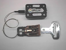
Figure 3. Typical mechanical assembly of seat belt buckle, showing electrical connection to Hall-effect sensor IC.
- Transient/ESD protection has been accomplished with the use of a 0.1 µF bypass capacitor welded between sensor IC supply and sensor IC ground. In the case of a PCB, an MOV has been used in addition to the bypass capacitor to protect the sensor IC against harsh EMC/ESD conditions due to the use of a chassis ground. Just a bypass capacitor may be sufficient when the sensor IC is robust against EMC/ESD.
- A sufficiently large magnet is required to overcome the shunting effect caused by the buckle assembly itself. SmCo and Neodymium are common magnet materials used in Seat Belt Buckle applications. They provide large field levels to compensate for the mechanical tolerances and possibly large air gaps > 3 mm) seen in SBB applications.
- Tolerances of the mechanical assembly can cause a large gauss variation (hundreds of gauss) in the field level impinging on the sensor IC; so all conditions must be characterized to ensure the sensor IC never switches into the incorrect state. The conditions that must not cause false switching of the Hall-effect sensor IC are as follows:
- Normal buckled position with the tongue in place.
- Normal unbuckled position with the tongue removed.
- Over-travel of the tongue when pushed in and held by a person sitting on it, or by a child seat resting on the buckle assembly.
- False latch condition when something other than the actual tongue is pushed in, holding the buckle in a falsely latched condition (popsicle stick, toy, etc).
Suggested Devices
Allegro™
Part NumberTemperature
RangePackage Type Tape & Reel
AvailableA115x EL LH, UA Yes A119x E, L LH, UA Yes