Using the A1330 in a Short Stroke Application
By Trevor Buys and William Wilkinson,
Allegro MicroSystems, LLC
Abstract
This application note is a guide for using the A1330 angle sensor IC for short stroke rotational position sensing, including information on magnet choice and orientation. It will outline the procedure for setting the EEPROM registers needed for A1330 short stroke applications. Two appendices are included, one that illustrates valid short stroke outputs and functionality, and one that describes in full how to use the Short Stroke Trim Tab in the Samples Programmer GUI.
Introduction
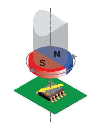
Accurate, low-cost, and noncontact rotational position sensing is often achieved using a diametric puck magnet and a magnetic sensor IC. The magnet is attached to the rotating object and the sensor IC is positioned such that the face of the magnet rotates parallel to the face of the sensor IC package (see Figure 1). Short Stroke (or fine angle scaling) is defined as magnetic angle rotations less than 360° to be represented by a full-scale output from the IC. Achieving full-scale output on sub-360° rotations allows the user to use the entire dynamic range of the ADC. Applications that are
often ideal for short stroke include:
- pedal position
- fuel tank level sensing
- gear position
- throttle and/or valve position
- actuator position
The Allegro A1330 magnetic angle sensor IC is well-suited for short stroke rotational position sensing because it provides advanced features such as:
- Analog/PWM Output: This configurable output allows easy reading and validation.
- High and Low Angle Clamps: Adjustable output saturation is highly configurable.
- User-Configurable Gain and Offset: To achieve full-scale output with little input change, GAIN and PREGAIN_OFFSET provide the ideal solution.
- Minimum and Maximum Angle Detection: Setting a minimum and maximum angle in EEPROM can provide a diagnostic check. It verifies the magnet is in a valid operating position.
Basic System Configuration
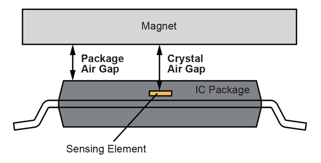
The A1330 is available in an 8-pin TSSOP package, single or stacked dual-die (recommended for systems requiring redundancy), and measures the angle of the magnetic field in the plane of the package. With the magnet mounted directly above the package (as shown in Figure 2), two different air gap definitions can be used: Crystal Air Gap and Package Air Gap. For the remainder of this document, Package Air Gap is used to refer to air gap. The CVH (Circular Vertical Hall) is located directly in the center of the single die package and the two CVHs (in the dual die package) are near the center (see datasheet for specific measurement details).
Designing the Magnetic System for Rotational Sensing
The appropriate magnet size and nominal air gap is a key component in angle sensing. The A1330 can sense magnetic fields up to 1200 G, which means larger magnets can be used to diminish any unwanted effects that stray fields may have on the system. In the event that the field strength is above 1200 G, no damage will be incurred on the device. Operating the A1330 in large magnetic fields will also lower noise, improve angle accuracy, and increase the effective resolution on the output signal of the IC. For additional information on noise performance, refer to the Noise section found later in this document.
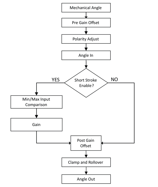
Short Stroke and Programming Parameters Depending on the end application and system requirements, different parameters may be more essential than others. The following are the available programmable settings for short stroke applications. The short stroke (SS) bit must be enabled to adjust the GAIN and MIN/MAX_INPUT registers.
Figure 3 represents a simplified version of the short stroke flowchart and Table 1 are the available short stroke registers and locations in EEPROM.
Table 1: Short Stroke Registers
| Register Name | Short Hand Name | Address | Bits |
| Pregain Offset | PREGAIN_OFFSET | 0x3A | 23:12 |
| Short Stroke Enable | SS | 0x3B | 25 |
| Gain | GAIN | 0x3B | 12:0 |
| Clamp Enable | CE | 0x3C | 25 |
| Rollover Enable | ROE | 0x3C | 24 |
| Maximum Input | MAX_INPUT | 0x3C | 23:12 |
| Minimum Input | MIN_INPUT | 0x3C | 11:0 |
| Polarity Adjust | PO | 0x3D | 24 |
| Postgain Offset | POSTGAIN_OFFSET | 0x3D | 23:12 |
| Low Clamp | LOW_CLAMP | 0x3D | 11:0 |
| High Clamp | HIGH_CLAMP | 0x3D | 5:0 |
PREGAIN_OFFSET
PREGAIN_OFFSET allows the angle to be zeroed, or remapped to the magnet’s current location, prior to the application of the gain. Often this is the first register that is programmed regardless of stroke. PREGAIN_OFFSET is a 12-bit value (0-4095) located in EEPROM 0x3B bits 13:24 with a resolution of 0.088°/bit.
POLARITY ADJUST
POLARITY ADJUST (PO) sets the polarity of the final angle output. When set to ‘0’, the Angle In is the mechanical angle, essentially bypassing this block. When set to ‘1’, the angle is complemented (See Equation 1). POLARITY ADJUST is a single bit located in EEPROM 0x3D bit 24. It is recommended to set the PREGAIN_OFFSET prior to setting the POLARITY ADJUST. This is due to the fact that PREGAIN_OFFSET changes the observed zero angle.
Equation 1: Polarity Adjust
Angle In = 360° – Mechanical Angle
MIN_INPUT and MAX_INPUT
The IC compares the pregained angle value to the boundaries set via the MIN_INPUT and MAX_INPUT EEPROM fields. In the event the angle is outside of the established boundaries, the output will tristate to indicate an error caused by an unexpected angle value. For this feature to work properly, either a pull-up or pull-down resistor will need to be connected to the output. The orientation of the resistor is dependent on the desired configuration of the ECU.
This feature is useful for applications where clamping is enabled and will otherwise mask excessive angular travel. MIN/MAX_INPUT are 12-bit values located in EEPROM 0x3C with a resolution of 0.088°/bit.
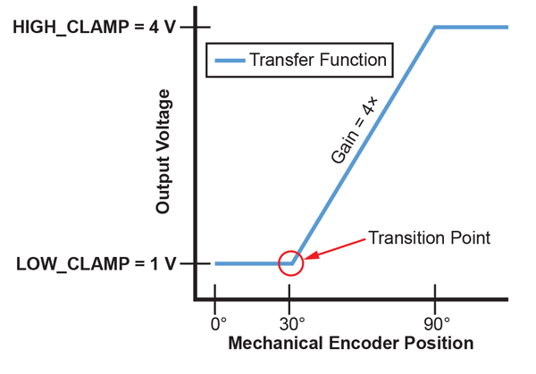
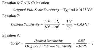
GAIN
GAIN adjusts the output dynamic range of the device by adjusting the slope of the output transfer function (mV/°). GAIN is applied digitally and is capable of expanding an 11.25° input angle to a full-scale output rotations (32×).
It should be noted in applications with high GAIN, the front end noise will be proportionally amplified. In such cases, it is highly recommended to use the Angle Averaging feature to minimize the impact of noise (this is referenced later in this document). GAIN is a 13-bit value located in EEPROM 0x3B bits 0:12 with a resolution of 0.0039× per bit of additional gain, i.e. code 1 = 1.0039× of the original signal.
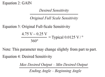
Calculating GAIN
POSTGAIN_OFFSET
POSTGAIN_OFFSET is similar to PREGAIN_OFFSET with one small caveat: it is used to offset the angle after the gain has been applied. This register moves the output signal away from the 0° position. See Figure 4 for graphical description and Equation 5 for calculation. Often, POSTGAIN_OFFSET is used as a buffer at the mechanical extremes. POSTGAIN_OFFSET is a 12-bit value located in EEPROM 0x3D bits 11:23 with a resolution of 0.088°.
In order to get the desired delayed transition point, use Equation 5 below. Figure 4 is a graphical representation of how POSTGAIN_OFFSET functions.
Equation 5: POSTGAIN_OFFSET
(Desired Mechanical Offset from 0° × GAIN Value) – Low _Clamp (°)
Achieving Figure 4 using Equation 5:
POSTGAIN OFFSET = (30° × 4) – 60°
POSTGAIN OFFSET = 120° – 60°
POSTGAIN OFFSET = 60°
Therefore based on Figure 4, in order to achieve 30° offset from the zero angle, 60° of POSTGAIN_OFFSET will be required.
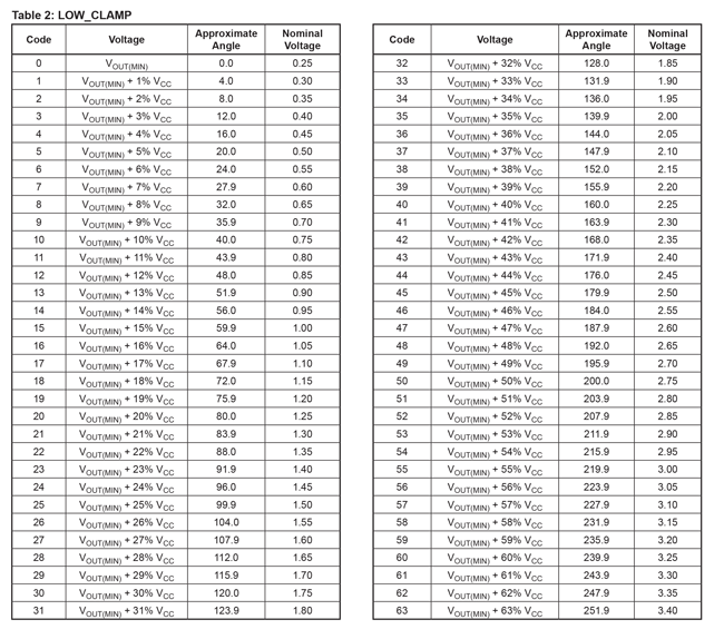
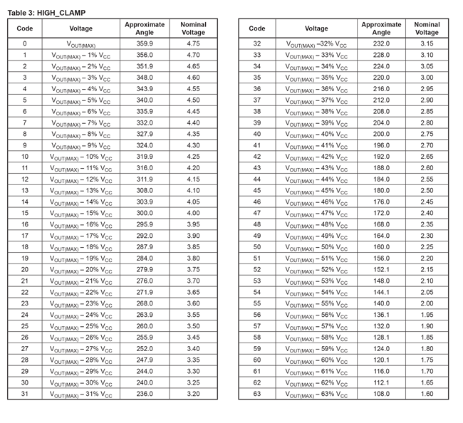
LOW_CLAMP AND HIGH_CLAMP
The LOW_CLAMP and HIGH_CLAMP specify the minimum and maximum output voltage swing (or PWM duty cycle); by default these values are set to 5% and 95% of VCC. Refer to Table 2 and Table 3 for the appropriate code for output clamps. Often, LOW/HIGH_CLAMP values are referred to in volts; however, they can also be thought of in terms of pregain (mechanical) valued angles. Both LOW_CLAMP and HIGH_CLAMP are 6-bit unsigned values, located in EEPROM 0x3D, bits 0:5 (LOW_CLAMP) and 6:11 (HIGH_CLAMP).
Clamp Enable and Rollover Enable
Rollover Enable (ROE) is a programmable setting which allows the output to return to a low state after reaching the high state (or vice versa). This can be done with or without a clamp. The Clamp Enable bit (CE) enables the HIGH/LOW_CLAMP to be adjusted and by default they are set to 5% and 95% of VCC. The rollover and clamp enable (CE) bits are located in EEPROM 0x3C, bits 24 and 25 respectively. Refer to Table 4 for the various iterations of clamps and rollover. Figure 5 and Figure 6 compare the output with and without clamping/rollover.
Table 4: Clamping and Rollover Selection
| CE | ROE | Description |
| 0 | 0 | Normal behavior. Rollover at standard module 360. |
| 0 | 1 | Output rollover at the High and Low Clamp values. |
| 1 | 0 | Output clamps at the first encountered High/ Low Clamp value. |
| 1 | 1 | Rollover occurs at standard module 360. Output is clamped to High/Low Clamps value. |
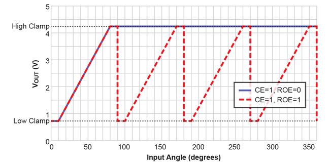
Figure 5: Clamping With and Without Rollover
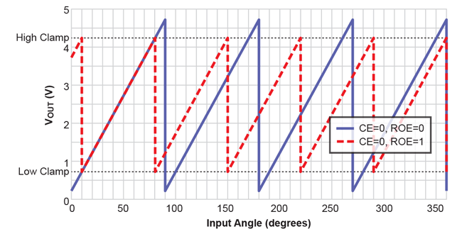
Figure 6: No Clamping With and Without
Rollover Enable
Note that in Figure 6, there are more high to low clamp values than shown in Figure 5; this is due to the LOW_CLAMP and HIGH_CLAMP. The settings used to create Figure 5 and Figure 6 were:
Table 5: Clamping Settings
| Register Name | Code | Value |
| PREGAIN_OFFSET | 0 | 0 |
| GAIN | 768 | 4× |
| LOW_CLAMP | 10 | 40° |
| HIGH_CLAMP | 10 | 320° |
Short Stroke Example
Programming the A1330 in a short stroke application can be done using ASEK20. For more information regarding the ASEK20, refer to the Allegro A1330 Samples Programmer User Manual. Figure 7 is the output for this example configuration. The output profile will hold a low clamp (1 V and 0.5 V) until 20° of rotation has occurred, then each die will ramp at different rates (50 mV/° and 25 mV/°) for an additional 60°, at which point the two dies will hold a high clamp for 20°
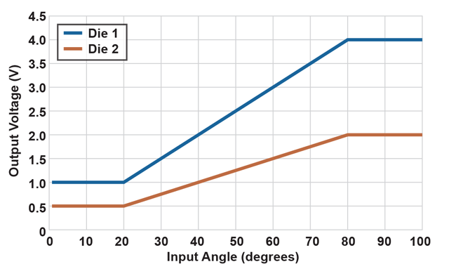
Figure 7: Example Application Output
There are two methods to program the A1330 using the Samples Programmer. The first method is to use the Short Stroke Trim tab (see Figure 8). This method will be covered in Appendix B. The other method is through the EEPROM tab. By using the EEPROM tab, registers not available in the Short Stroke Trim tab are made available.
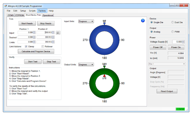
Figure 8: Short Stroke Tab
Figure 7 is an example of a commonly used pedal position output. Die 2 is set to be 50% of Die 1; this is often for safety requirements. The microprocessor will verify the angle readings by dividing Die 1 from Die 2.
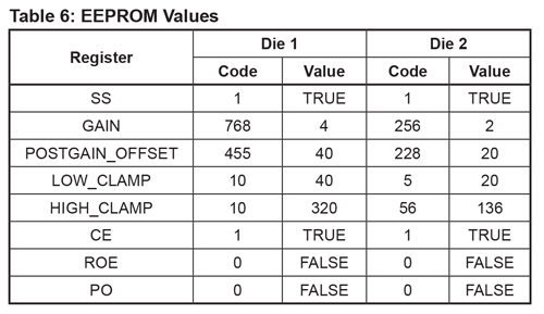
The A1330 must meet these specifications:
Table 6: EEPROM Values
Programming Procedure
1. Start the Programmer and Setting the Zero Angle:
a. Connect the A1330 to the ASEK20 (see Figure 9), and connect the ASEK20 to your computer.
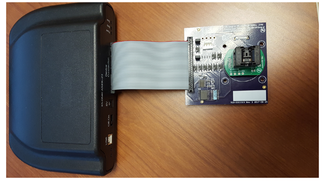
Figure 9: A1330 on a Daughter Card plugged into an ASEK20
b. Start the Samples Programmer software and power on the A1330. With the magnet above the A1330 package, press the power on (using a button on the right side of the GUI). Read the output by pressing either the ‘Read Output’ (located on the right), ‘Read Once’ (located top left of the GUI) or ‘Start Reads’ (located at the top left of the GUI; this will poll the sensor at even intervals from EEPROM).
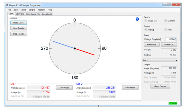
Figure 10: A1330 Sample Programmer Demo Tab
c. To remap the A1330 to the 0° position at the magnet’s current angle location, use the ‘Zero Angle’ button located at the bottom left of the window. This will adjust the PREGAIN_OFFSET register value and reassign 0° to this location.
2. EEPROM Programming: The EEPROM tab contain all the registers that are available to the user. The pull-down menu located near the top left can be adjusted to All Memory Locations, All Fields, or Short Stroke Fields. Select Short Stroke Fields.
a. Short Stroke Fields: The Short Stroke Fields menu selected on the EEPROM tab contains the collection of registers meant for short stroke applications. In order to achieve the example application, apply the values found in Table 7 into the EEPROM registers. Figure 11 and Figure 12 are the actual values found in EEPROM.
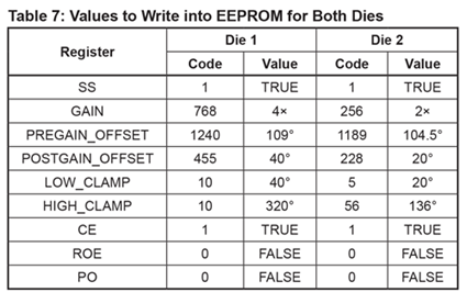
Note: The PREGAIN_OFFSET value was the initial angle read from the A1330 prior to any gain or clamp values.
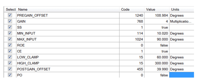
Figure 11: Die 1 (Full Scale) Short Stroke
EEPROM Settings
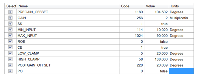
Figure 12: Die 2 (Half Scale) Short Stroke
EEPROM Settings
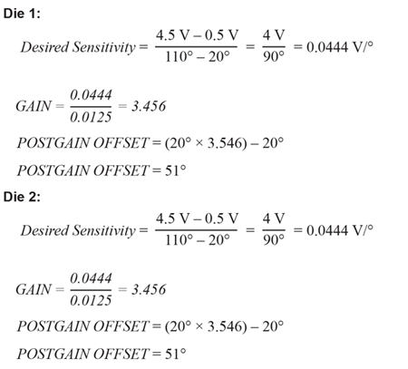
3. Verify the Output: In order to verify that the EEPROM settings were correct, connect DMMs (Digital Multimeter) to the outputs and sweep the angle rotation. Any adjustments that need to be made to the transition points should be done by changing the POSTGAIN_OFFSET. POSTGAIN_OFFSET is directly correlated to the GAIN value, for instance, in order to get 1° mechanical change for Die 1, roughly 4° of POSTGAIN_OFFSET is needed.
Therefore, these are the needed values for POSTGAIN_OFFSET:
Die 1 (Full Scale)
POSTGAIN_OFFSET = (20° × 4) – 40° = 40°
Die 2 (Half Scale)
POSTGAIN_OFFSET = (20° × 2) – 20° = 20°
Often, POSTGAIN_OFFSET is used as a buffer at the mechanical extremes.
4. Setting Minimum and Maximum Input: Setting minimum and maximum input limits on the system serves as a warning to the user that the magnet has gone into a position it was not intended to travel. These values for minimum and maximum input are pregain values; therefore, with this example, appropriate values might be:
- MIN_INPUT = 10°
- MAX_INPUT = 90°
If the magnet goes into either range (i.e. below minimum input, 10°, or above maximum input, 90°) then the output tristates. Once the magnet returns to an appropriate angle, then the output will return to normal operation.
Results
The magnet used in the application example was an 8 mm (width) × 3 mm (thickness) N35 nickel-plated rare-earth magnet that was magnetized through the diameter; see Figure 13 for the magnet strengths over different air gaps. The air gaps tested were between 1 mm and 1.5 mm.
The following are results and data gathered using the settings in the previous section.
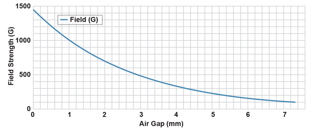
Figure 13: Measured Field Strength over Air Gap with an 8 mm Disc Magnet
Angle Accuracy
Determining the accuracy of the A1330 Short Stroke requires an ideal case. In this application note, the curves shown in Figure 7 will be considered ideal, zero error output curves. For an accurate comparison, only the linear slope will be considered (minus the two transition points).
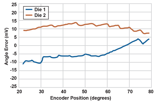
Figure 14: Angle Accuracy over Encoder Position
Figure 14 was calculated using Equation 9 below:
Equation 9: Angle Error
Error Die 1 = Ideal Die 1 – Measured Die 1
Error Die 2 = Ideal Die 2 – Measured Die 2
The nominal sensitivity for the A1330 is roughly 12.5 mV/°; however, because each die has a different gain value, the sensitivity changes accordingly. For Die 1, output the new sensitivity is 50 mV/° and the sensitivity for Die 2 output is 25 mV/°. Therefore, in order to be within 1° of angle error, each output must be within 50 mV and 25 mV of the ideal output, respectively.
The Die 1 output has a maximum error of 11 mV and the halfscale output has maximum error of 13 mV. Therefore, each output is considerably under 1° of error, that is, 0.22° error for Die 1 and 0.52° error for Die 2.
0
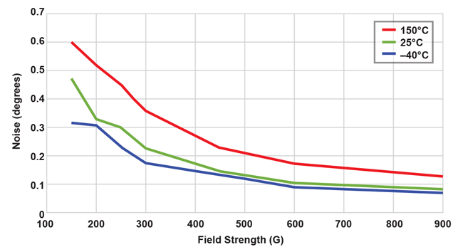
Figure 15: Noise (1 σ) vs. Field Strengthover Temperatures (ANG_AVG = 0)
Depending on the end application and the speed at which the output of the sensor needs to be sampled, adjusting the Angle Averaging register can significantly reduce the noise on the output of the IC (see Table 8 and Figure 16), as well increasing the overall field strength observed by the A1330 (see Figure 16). For the example, in this document, an ANG_AVE set to 000 was used, meaning data was refreshed every 25 μs at the output of the IC, and had between 8-10 ENOB. For most applications, setting the ANG_AVE = 4 would be more than adequate, as it would provide a fast enough refresh rate for the user and would lower the noise.
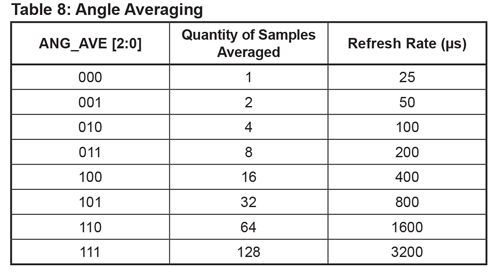
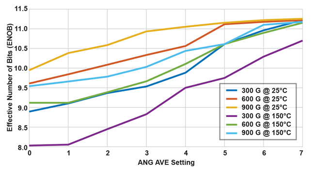
Figure 16: Measured ENOB at Various Fields and Temperatures
Conclusion
The A1330 magnetic angle sensor IC works well in short stroke applications when one needs a full-scale output in sub-360° magnet rotation. The CVH-based angle sensor ICs, specifically the A1330, are well-suited for short-stroked applications, as they can operate in low and high magnetic fields. The small, 8-pin TSSOP package is great for applications with limited PCB space. The A1330 provides adjustable internal averaging, allowing response time to be traded for resolution. With minimal components needed external to the sensor IC, the A1330 is a low-cost solution for any short stroke application.
APPENDIX A
This appendix highlights an additional Short Stroke configurations that the A1330 can accomplish. Note this configuration is a generic iteration of an actual output.
CONFIGURATION A
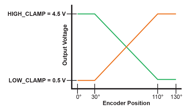
Figure 17: Output of Configuration A
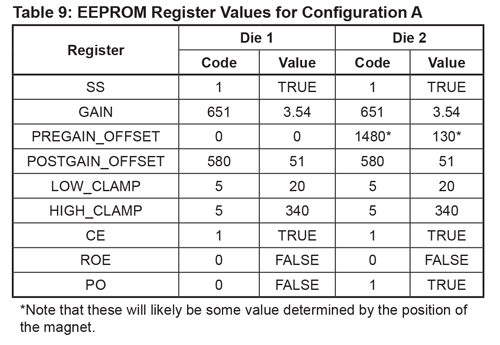
Configuration A is a common output for throttle position sensing. When added together, the outputs always result in the same value. This adds redundancy that is often required for safety requirements. A check within the microprocessor can verify the outputs and alert the user if there is an issue.
To achieve Configuration A, follow these steps:
- Connect the ASEK20 and use the A1330 software found on the software portal.
- Verify that the COM port is communicating with the software. This can be seen by a green bar in the lower right of the software window. If the bar is red, click on it and a new window will appear. Select the correct COM port and click ‘OK’.
- Select the dual die and analog or PWM output. Power on the device by clicking ‘Power On’ located on the right of the window.
- With a magnet in place, select ‘Read Output’. This will indicate what the magnet is currently reading. Select ‘Zero Offset’ to remap the A1330’s 0° angle reading to the current magnet angle location. This will be apparent if you read the EEPROM registers, specifically PREGAIN_OFFSET.
- Select the ‘EEPROM’ tab. On the pull menu, select ‘Short Stroke Fields’. This shows just the registers that pertain to short stroke.
The following are the registers and values needed to create Configuration A (see Table 9 for complete EEPROM register values):
APPENDIX B
The Short Stroke Trim tab is a gateway into programming the A1330 for short stroke outputs. This appendix will highlight the main points of the Short Stroke Trim tab (Figure 18). Some registers are not available in this tab, namely, POSTGAIN_OFFSET, POLARITY ADJUST, and MIN/MAX_INPUT. In order to adjust those registers, refer back to the main document.
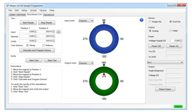
Figure 18: Short Stroke Trim Tab
PROGRAMMING THE A1330 USING THE SHORT STROKE TRIM TAB
- With the Allegro A1330 Samples Programmer open, COM connected (indicated by a green box in the lower right corner of the window), device powered on, and the magnet located directly over the device, navigate to the Short Stroke Trim tab in the upper left corner of the window. There are two methods as to how to think of the output, either in degrees or in volts. For the purpose of this walkthrough, the output units will be in volts. This can be manipulated by adjusting the pull-down menu next to Output Units. By changing the output units (and input units) from degrees to volts, the values stored in Position 1 and Position 2 will be adjusted to the correct corresponding values (i.e. 359° ≈ 4.75 V).
- With the output units changed to volts, the window will look like Figure 19. Located in the ‘Trim’ box are several options:
a. Start/Stop Reads
i. This method reads, in real time, the smallest and largest angle value from the magnet rotation. This can be used as an alternative to putting in values in the Input Positions. It will automatically populate Position 1 and Position 2 for Input.
b. Input Position 1 and 2
i. The Input Positions are pregain value in either degrees or volts of the rotation of the magnet.
c. Desired Position 1 and 2
i. Desired Position determines the GAIN of the system.
d. Limits Position 1 and 2
i. This adjusts the HIGH_CLAMP and LOW_CLAMP values.
e. Limit Actions – Clamp and/or Rollover
i. Activates clamping, rollover, or both.
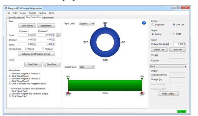
Figure 19: Short Stroke Trim Tab – Output Units Volts
3. With the output set to the desired values (see Figure 20 for example), select ‘Calculate and Program Device’. This will set the appropriate EEPROM registers for the desired output.
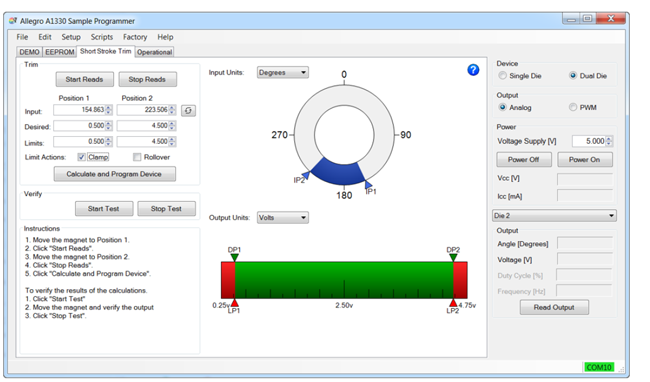
Figure 20: Adjusted Values in the Short Stroke Trim tab
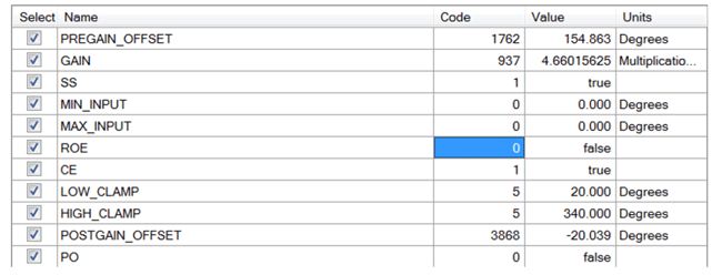
Figure 21: EEPROM Settings
4. Finally, to verify the output is correct select ‘Start Test’ within the Verify box. A gray line on both Input Value and Output Value will appear. As the magnet rotates the gray line will move on both bars in respect to the gain value. By moving to the Operational tab and selecting ‘Start Reads’, a plot of the voltage in respect to time will appear. This can be used as an additional verification for the desired output.