Increasing System Safety using the A1365 Programmable Linear Hall-Effect Sensor IC with Self-Test Diagnostic Mode
By Wade Bussing, Applications Engineer,
Allegro MicroSystems, LLC
Abstract
This application note provides guidelines for implementing the Self-Test Diagnostic mode on the A1365 from Allegro MicroSystems in order to verify system functionality and safety in the application. To learn more about the A1365 from Allegro MicroSystems, refer to the device’s datasheet at www.allegromicro.com.
Introduction
The advent of Automotive Safety Levels has spurred an increase in safety requirements, making IC and sensor safety features as important as the target performance specifications in some applications. As safety goals multiply throughout the system design process, customers demand smart sensors that can be used to diagnose abnormalities in a system. The built-in Self-Test mode of the A1365 grants users such insight into their systems.
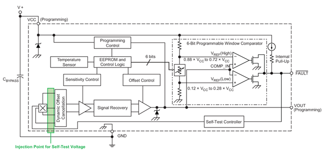
The Self-Test mode on the A1365 covers the entire signal path, from the analog output (VOUT) and FAULT output pins up to the connections to the Hall transducer. Refer to the block diagram of the A1365 in Figure 1 which highlights the injection point of the on-chip test voltage in green.
The A1365’s Self-Test mode allows the user to verify, at any point, connectivity of the analog signal path, drifts in quiescent output voltage, as well as connectivity and functionality of the Over Field Fault signal path. By comparing the voltages and various timings measured during the Self-Test mode, the user can also evaluate the integrity of any external devices, including system ADCs and overcurrent fault control devices. The Self-Test Fault feature simplifies end-of-line verification of overcurrent fault circuitry external to the A1365 without the burden of injecting large full-scale
currents.
The Self-Test mode is intended to reveal gross single point failures in the Hall path, but does not test the sensitivity of the Hall transducer itself.
Enabling the Self-Test Mode
The Self Test feature is disabled in all sales versions of the A1365 IC. However, the test mode is easy to enable using the Allegro A1365 Samples Programmer and an ASEK evaluation board. The A1365 Samples Programmer is available on Allegro’s software portal at https://registration.allegromicro.com. Contact your sales representative for information on acquiring an ASEK evaluation kit.
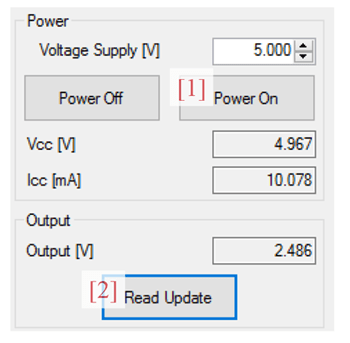
To enable the Self-Test mode on the A1365, power-on the device by pressing the “Power On” button [1] on the A1365 Samples Programmer shown in Figure 2. Confirm that the device is operational
by verifying VCC, ICC, and Output values are reading as expected using the “Update” button [2].
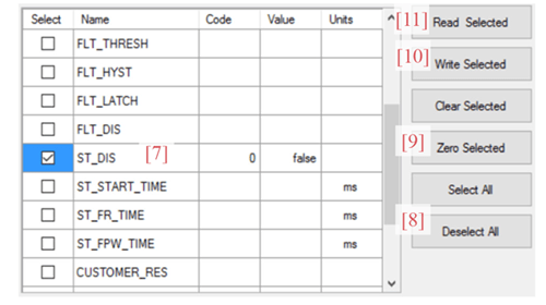
The “Memory” panel on the programmer displays all available registers on the A1365 device, along with a brief description of each register’s function [3]. Refer to Figure 3 for more information.

A1365 Samples Programmer
Choose the “Select All” button [4], followed by the “Read Selected” button [5], which will read back the memory contents of the device and populate the code and value columns with the returned data. Prior to making any changes to the device’s memory, it is best practice to save a local copy of the EEPROM contents to revert back to. Choose the “Save” button [6] to generate either a .csv or .txt file for safekeeping.
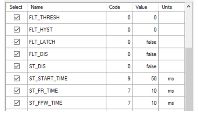
To enable the Self-Test mode, refer to Figure 4. Scroll down to the field “ST_DIS” (self-test disable) [7], choose the “Deselect All” button [8], then select only the “ST_DIS” field using the checkbox. Set the “ST_DIS” code column to “0” by typing “0” into the cell, or choosing the “Zero Selected” button [9] on the GUI. When ready, press the “Write Selected” button [10] to write the new value to \ EEPROM. It is best practice to read back the same register to verify the change. Choose “Read Selected” [11] to confirm the “ST_DIS” bit has been cleared. The Self-Test mode is now enabled.
A1365 Samples Programmer
Initiating the Self-Test Mode
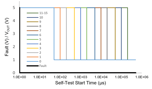
Once enabled, the Self-Test mode may be initiated by pulling the A1365’s FAULT pin low. The device does not enter the Self-Test mode immediately; the FAULT pin must be held low for a time period greater than the “Self-Test Start Time” to enter the Self-Test diagnostic mode. The Self-Test Start Time is programmable and is designated in the programming field “ST_START_TIME”. There are sixteen codes which correspond to twelve discrete Start Time values.
The available codes for Self-Test Start Time and their corresponding time delays are listed in Table 1.
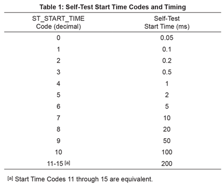
Self-Test Start Time is defined from when the FAULT pin voltage (VFAULT) falls below the Self-Test Threshold Voltage (VSTTH) until the sensor enters the Self-Test Sense mode. The sensor enters Self-Test Sense mode by driving the analog output to Self- Test Low Voltage (VSTL). If at any point during Self-Test Start Time the sensor detects a magnetic input exceeding the programmed fault threshold, the Self-Test timer will reset.
The plot in Figure 5 shows the time for VOUT to reach VSTL after the FAULT pin is pulled low for all Self-Test Start Time codes on the A1365.
Self-Test Fault Request Time
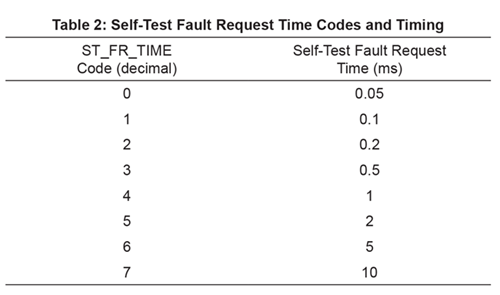
Self-Test Fault Request mode allows the user to verify the userprogrammed fault thresholds on the A1365. The device will enter Self-Test Fault mode after the FAULT pin is released for a time longer than Self-Test Fault Request Time (ST_FR_TIME).
After the pin is released, but prior to Self-Test Fault Request time expires, the output is driven to Self-Test High Voltage (VSTH). As the device enters Self-Test Fault Request Mode, the output of the
device is driven to saturation (VSAT(HIGH)).
The available codes for Self-Test Fault Request Time (ST_FR_TIME) and their corresponding delays are listed in Table 2.
In Self-Test Fault mode, the A1365 will drive VOUT into saturation, both VSAT(H) and VSAT(L). When VOUT crosses the user-programmed fault thresholds (FLT_THRESH), the sensor’s FAULT pin will assert to indicate a fault condition. Note that this mode temporarily disables the clamps if the clamps are enabled.
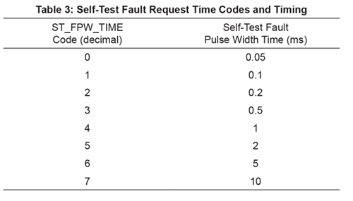
Self-Test Fault Pulse Width Time
The A1365 will drive and hold VOUT to each test voltage for a period defined by Self-Test Fault Pulse Width Time (ST_FPW_TIME). The available codes for Self-Test Fault Pulse Width Time and their corresponding pulse width times are listed in Table 3.
Complete Self-Test Mode Sequence
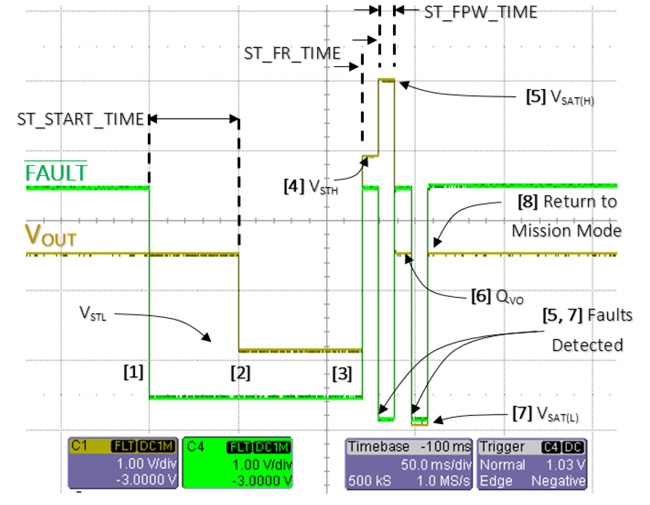
The entire Self-Test mode sequence is shown in Figure 6. The applied magnetic field during the Self-Test Mode must be zero.
for the Sequence in Figure 6
The Self-Test sequence is described in the list below. Each step corresponds to a point in time on the plot in Figure 7.
- The A1365’s FAULT pin is pulled low externally to initiate the Self-Test mode. The A1365 would still properly respond to magnetic fields at this time.
- The device enters Self-Test Sense mode after ST_START_ TIME and drives VOUT to VSTL.
- VOUT remains at VSTL until the FAULT pin is released.
- VOUT is driven to VSTH for the duration of Self-Test Fault Request Time, ST_FR_TIME.
- The device enters Self-Test Fault Request mode and VOUT is driven to VSAT(H) for ST_FPW_TIME and the FAULT pin is asserted.
- VOUT is driven to QVO for ST_FPW_TIME (10 ms) and the FAULT pin resets.
- VOUT is driven to VSAT(L) for ST_FPW_TIME (10 ms) and the FAULT pin is asserted.
- The Self-Test Sequence is complete and the device returns back to normal operation (mission mode).
Application Case
The Self-Test mode on the A1365 may be used to verify gross anomalies and single point failures on the A1365 device. This feature may also be used to confirm the integrity and timing of other system devices, including ADCs and fault control circuitry.
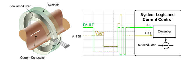
The application schematic in Figure 8 shows such a system. The A1365 is installed in the gap of a laminated core and is used to sense magnetic field generated by current flow in a conductor. The analog output, VOUT, is connected to an ADC while the FAULT pin is connected to a general purpose I/O pin on the microcontroller. Assume the I/O-connected FAULT pin signals a system interrupt in the event of an overcurrent condition. This interrupt prompts the microcontroller to put the system in a safe state by disconnecting current flow in the conductor.
Copyright ©2018, Allegro MicroSystems, LLC
The information contained in this document does not constitute any representation, warranty, assurance, guaranty, or inducement by Allegro to the customer with respect to the subject matter of this document. The information being provided does not guarantee that a process based on this information will be reliable, or that Allegro has explored all of the possible failure modes. It is the customer’s responsibility to do sufficient qualification testing of the final product to insure that it is reliable and meets all design requirements.