Advanced Algorithm Minimizes Stepper Motor Noise and Vibration in Precision Motion Control Applications
Stepper Motors: Benefits and Challenges
Stepper motors offer unique advantages over direct current (DC) and brushless DC (BLDC) motors in many applications. A bipolar stepper provides accurate open-loop position as well as zero-speed torque without using a control loop or external sensors. With their controlled stepping capabilities, stepper motors are ideal for a wide range of precision motion control applications including closed-circuit TVs (CCTV), 3D printers, computer numerical control (CNC), textile manufacturing equipment, and pick-and-place machines.
Successful deployment of stepper motors requires effective management of noise and vibration. In CCTV applications, for example, vibration translates directly to the image sensor and gimbal. Large zoom combined with movement can distort the image. In 3D printing, motor resonance or overshoot caused by high torque ripple can result in many unwanted printing artifacts. In most cases, reducing motor vibration results in better image quality or more precise 3D printing. Reducing motor vibration also enables quieter overall operation.
Advanced technologies based on proprietary algorithms—such as QuietStep found in Allegro’s A5984 microstepping motor driver—are now available to minimize noise and vibration in stepper motor designs by reducing torque ripple and current distortion. Before delving into these motion control solutions, it’s helpful to understand what causes vibration and in turn audible noise, starting with how a stepper motor operates.
Stepper Fundamentals
A bipolar stepper motor is a DC motor with discrete pole positions constructed of multiple coils arranged in two groups called phases. The current ratio between the two phases determines how the rotor is positioned between the two windings. In this way, a stepper motor can divide its position between two poles into smaller increments called microsteps.
The current in each stepper motor winding can be summed to create a vector where the magnitude of the vector is the torque. By examining the current in each of the two phases in polar space, the vector can be visualized as it rotates through each electrical cycle.
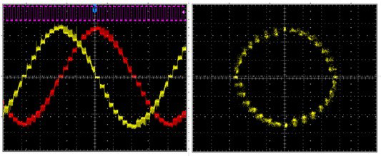
Figure 1. Left - Phase current in each of two windings of a bipolar stepper motor in 1/8th step.
Right – Phase current in each of two windings of a bipolar stepper in 1/8th step but represented in the polar domain.
In the time-based domain (Figure 1, left), the torque is defined as the sum of the area under the two curves. In the polar domain (Figure 1, right), the magnitude of the vector is the torque. In these images, the torque can be seen as constant as the field moves through each electrical cycle. When torque is not constant, the system experiences vibration and audible noise.
Assuming the motor is not operating at resonance, torque ripple becomes the biggest source of audible noise and vibration in a stepper motor.
Controlling a Stepper Motor (Current Control)
Pulse-width modulation (PWM) current control is the most common way to drive a stepper. By implementing current control, the controller PWM chops the output, limiting the current in each winding to maintain a ratio that defines the rotor position.
The nature of PWM current control results in current ripple based on the applied duty cycle, the inductance of the motor, and the voltage across it. To minimize ripple, the controller can manage how the current decreases in the windings by implementing various decay modes.
Common decay modes for a single PWM cycle begin with drive current ramp-up.
Following the drive, shown in figure 2A, the decay mode is implemented during PWM off-time through two synchronous methods shown in figure 2B and 2C.
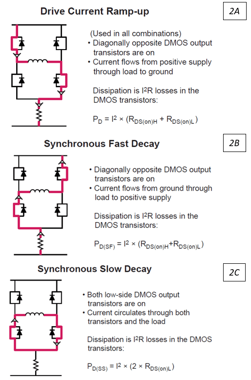
Figure 2: Current path in full bridge showing drive and decay modes.
Fast decay provides optimal current control but results in high ripple. Slow decay results in low ripple, but the rate of decay is subject to the motor’s back electromotive force (BEMF), which in some cases can create distortions in current.
Figure 3A shows what can happen when using 100 percent slow decay. When the winding current is falling, slow decay can’t decrease the current fast enough, causing distortion on the falling edge. Figure 3B shows the effects of using 100 percent fast decay. The ripple current is much larger, but the controller maintains accurate control of the current.
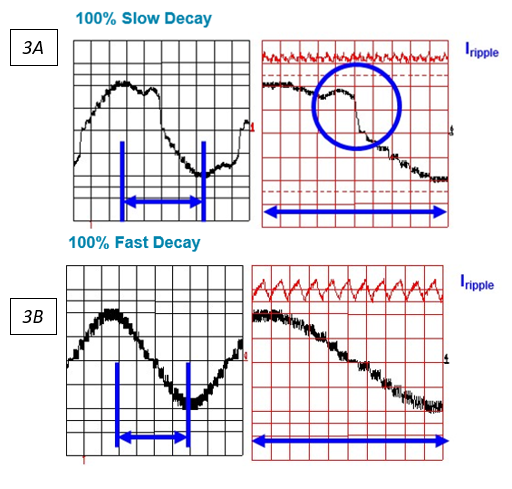
Figure 3A Slow decay can produce distortion when current in load is decreasing.
Figure 3B. Fast decay causes large ripple current, which can result in vibration and audible noise.
The effects shown in Figure 1 can be avoided while also maintaining reasonable ripple current by reaching a compromise. When the current is decreasing in the load, the driver implements a combination of fast and slow decay, known as mixed decay. The off-time is divided into a portion of fast decay and a portion of slow decay, as shown in Figure 4. When current in the load is increasing, slow decay minimizes ripple.
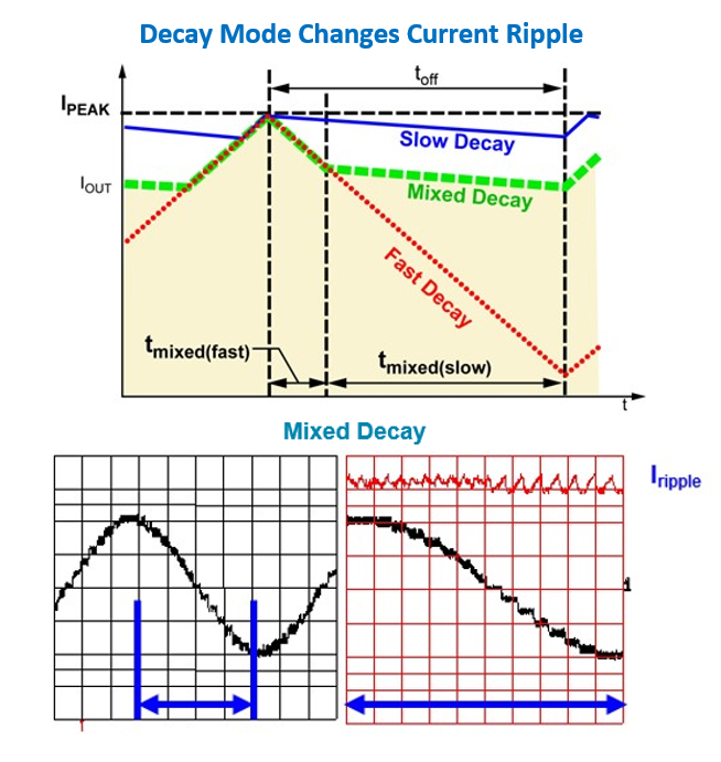
Figure 4. Mixed decay minimizes ripple while also maintaining control of the current in the winding.
Depending on a stepper motor’s characteristics and its LR time constant, slow decay on the rising edge can create issues at low currents where the rate of change in current is too fast for the PWM controller to regulate to low currents due to current sense amplifier blanking. This scenario can result in current distortion when the current in the load is increasing, as shown in Figure 5.
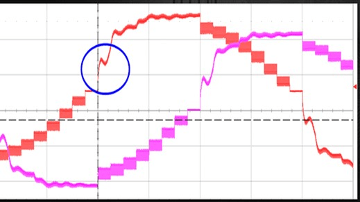
Figure 5. Slow decay on the rising edge can cause distortion in motors with certain LR characteristics.
It’s difficult to achieve an easy compromise that works for all bipolar stepper motors. To solve these issues while maintaining the lowest ripple possible, the system must adapt to different motor characteristics.
A New Approach to Reducing Torque Ripple
Allegro has introduced a novel way to reduce torque ripple and current distortion for stepper motor applications. This innovation, QuietStep, is now available as an option on Allegro’s latest A5984 stepper motor driver.
QuietStep technology uses a proprietary algorithm that dynamically adjusts (up or down) the percent of fast decay needed on a cycle-by-cycle basis to achieve the best possible performance under all operating conditions without using complex software.
The algorithm reverses the traditional approach to mixed decay by implementing slow decay first, followed by fast decay. Figure 6A shows traditional mixed decay with the fixed portion of fast and slow decay and with fast decay starting the PWM off-time cycle. Figure 6B shows how slow decay starts when using QuietStep at the beginning of the PWM off-time cycle. QuietStep automatically adjusts the ratio of fast and slow decay to minimize current ripple while maintaining accurate current regulation.
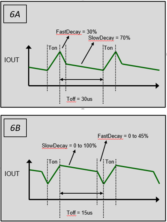
Figure 6A. Traditional mixed decay where the ratio of fast and slow decay is fixed.
Figure 6B. Adaptive-PFD can dynamically adjust the ratio of fast and slow decay to maintain current control and minimize current ripple.
Fast decay is introduced only when required for current regulation, resulting in the lowest possible ripple current. Figure 7 shows the high ripple current resulting from fixed mixed decay with decreasing current and loss of current control with slow decay with increasing current. QuietStep technology eliminates these effects, by cutting ripple current in half when compared with mixed decay. When current is increasing, QuietStep maintains current regulation down to zero amperes.
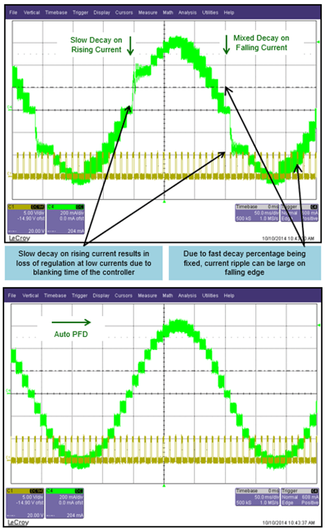
Figure 7. Traditional slow decay with increasing current and mixed decay for decreasing current results in loss of regulation on rising with increasing current and large ripple with decreasing current. Adaptive-PFD provides excellent current regulation with increasing current while maintaining low ripple current through the entire electrical cycle.
Reducing system-level current ripple and resonance minimizes vibration as well as audible noise caused by vibration. The result is better video imaging in CCTV systems and superior print quality in 3D printing.
Reducing audible noise and vibration enhances nearly every motor control application, from home automation door locks and valve control to precision vision systems and 3D printing. Allegro’s QuietStep technology removes the hassle of trying to determine the source of noise and vibration in a system. Fully integrated into the IC, QuietStep is easy to implement, requires no programming or external components, and is completely automatic.
Deploying QuietStep with Allegro’s Bipolar Stepper Motor Driver
With microstepping motor drivers enabling this advanced technology, like the Allegro A5984, current waveforms are automatically optimized over a wide range of stepper motor speeds and characteristics. Stepper motor driver solutions, equipped with QuietStep technology, adjusts the amount of fast decay on-the-fly during a PWM cycle to minimize current ripple over various operating conditions. This feature improves system performance, resulting in reduced audible motor noise, lower vibration, and increased step accuracy. Utilizing this technology, the A5984 driver is designed to operate bipolar stepper motors from full-step up to 1/32 step modes and enables an output drive capacity of up to 40 V and ±2 A. Overall, an QuietStep algorithm allows for easier system design, implementation and operation.
To learn more about the A5984 driver and QuietStep technology, visit www.allegromicro.com/a5984
Allegro MicroSystems is a global leader in power and sensing solutions for motion control and energy-efficient systems. For more information, visit www.allegromicro.com.
Based on the article, “Minimizing Stepper Motor Noise and Vibration in Precision Motion Control Applications” by Dan Jacques of Allegro MicroSystems, originally published by All About Circuits, February 2021. The original article can be found here. Used with permission. For portions not copyrighted by original publisher, Copyright ©2021, Allegro MicroSystems, INC.