Achieving Closed-Loop Accuracy in Open-Loop Current Sensors
By Shaun Milano,
Allegro MicroSystems, LLC
Closed-loop current sensing technology is employed in many industrial and automotive applications for accurate current sensing. By employing proprietary packaging techniques and advanced integrated algorithms in a single monolithic, fully integrated current sensor IC, Allegro MicroSystems, LLC has developed magnetic-based current sensor IC solutions that achieve near closed-loop accuracy using an open-loop topology. The packaging methods and algorithms used to achieve this are the topic of this paper and will be discussed in detail.
Open Loop vs. Closed Loop Current Sensing Topology
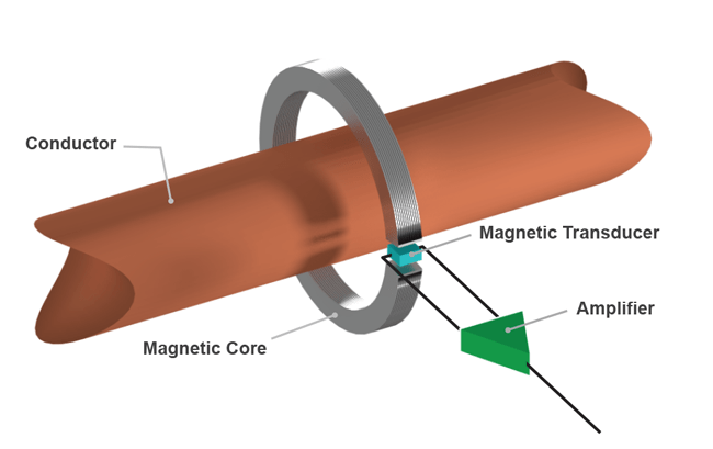
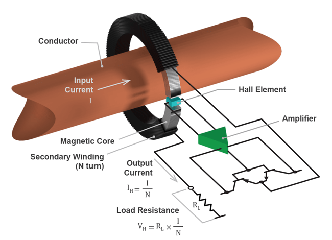
In general, an open-loop Hall-effect sensor employs a magnetic transducer to create a voltage that is proportional to the current being sensed. This signal is then amplified to provide an analog output signal proportional to the current flowing in the conductor. The conductor is fed through the center of a ferromagnetic core to concentrate the field and the magnetic transducer is placed in the gap of the core. This topology is shown in Figure 1. In an open-loop configuration, any non-linearity or drift in the sensitivity of the Hall-effect current sensor IC over temperature can produce error. A closed-loop sensor uses a coil that is actively driven by the current sensor IC to produce a magnetic field that opposes the field produced by the current in the conductor.
The Hall sensor then observes a net zero magnetic field at the transducer. The output is generated by a resistor that has a voltage proportional to the current being driven into the coil, which is also proportional to the current flowing in the primary conductor leveraged by the number of turns of the coil wound around the magnetic core. The closed-loop topology is shown in Figure 2. Closed-loop current sensors not only require ferromagnetic cores but also a coil and additional higher power amplifiers to drive the coil. While closed-loop current sensors are more complex than an openloop
configuration, they do eliminate the sensitivity error associated with the Hall sensor IC, since the system is being operated at just a single point at zero field. Closed-loop and open-loop Hall-effect current sensors generally have the same zero amp output voltage performance if designed properly, and so open- and closed-loop sensor zero amp detection accuracy are very similar. Closed-loop sensors are larger in size and take up more PCB area than open-loop solutions. They also consume more power as they need to drive the compensation coil and are more expensive because
of the additional coil and coil drive circuitry.
The choice of open-loop versus closed-loop sensing then becomes one of accuracy and response time required. If applications demand high accuracy, a closed-loop current sensor is often an easy and obvious choice as it removes the aforementioned sensitivity nonlinearity error in the system. The fast response time of closed-loop is required to protect semiconductor switches, like IGBTs and MOSFETs that are used to control current flow in the application. The challenge then becomes making an open-loop sensor with sufficient accuracy and speed that it becomes an option for these applications. Allegro has developed the technology to provide an open-loop solution with industry-leading small form factor, high accuracy, and speed that draw less current than closed-loop solutions at a lower price point, making them the new logical choice.
Open-Loop Sensor IC Packaging
Allegro current sensor ICs are unique in that most are fully integrated. Patented flip-chip packaging techniques are employed to create sufficient field to remove the need for a ferromagnetic
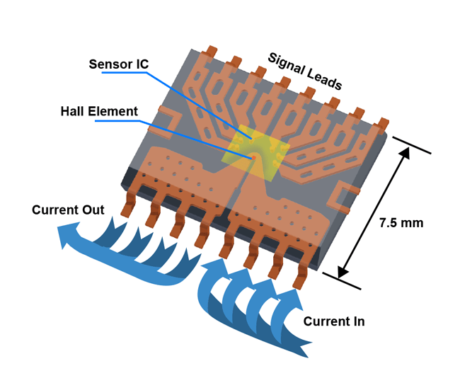
core. Figure 3 shows an SOIC16 current sensor IC configuration. Notice the current comes in and out of one side of the package and the signal leads are on the other side of the package. The
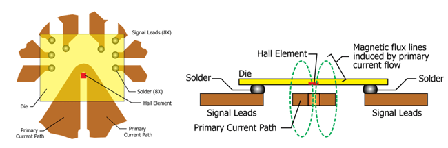
current generates a magnetic field that is focused at the center of the ¾ turn conductor seen in the top view of Figure 4. The IC is bumped, and a flip-chip assembly technique is employed to place
the magnetic Hall transducer over the area of maximum field.
The cross section view of Figure 4 also shows that there is no physical contact between the semiconductor IC and the current carrying conductor. This provides the galvanic isolation required
in many high voltage applications. Different package footprints will provide different levels of isolation as rated by a common and difficult UL and TUV specification UL/TUV60950-1 edition
2. See device datasheets at http://www.allegromicro.com/en/Products/Current-Sensor-ICs.aspx for isolation ratings of individual sensors. The conductor resistance of these surface mount packages is very low at only 1 mΩ. These packages can be used for continuous currents up to 50 A RMS or DC with nominal thermal considerations on the customer PCB. A detailed application note on package thermal performance for DC and transient currents is located at the following link. http://www.allegromicro.com/en/Design-Center/Technical-Documents/Hall-Effect-Sensor-IC-Publications/DC-and-Transient-Current-Capability-Fuse-Characteristics.aspx
Advanced Semiconductor Algorithms to Enhance Accuracy and Speed
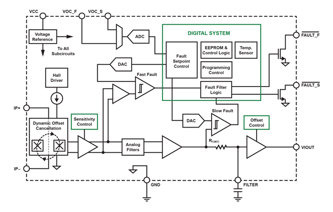
The Allegro ACS720 current sensor IC provides an excellent example of the new open-loop technology. Figure 5 shows a typical block diagram of the IC.
The Allegro BiCMOS mixed signal semiconductor process allows for low offset analog circuitry together with medium density digital circuitry, making it possible to integrate advanced algorithms onto a single monolithic integrated circuit. The analog signal path is designed to operate at 120 kHz bandwidth with a < 4 μs response time that works well in most motor control and green energy applications. For applications that require faster response times for protection against overcurrent faults, the ACS720 also has both a digital slow fault for overcurrent detection and a very fast digital fault current output for short circuit protection. The trip points for both fault outputs are user-configurable with a resistor divider on the VOC pins. The fast fault trips go active low in just over 1 μs and provide a signal that can be used to protect the semiconductor switches from shorting events. This provides the high speed protection needed for most applications.
The sensor also integrates features that are optimized for inverter applications where the power and signal boards are often powered by different supply voltages. The ACS720 internal regulator
operates on the 5 V power supply and has a large power supply rejection ratio that provides immunity to noise on the power rail. The output of the device however is nonratiometric and compatible
with 3.3 V supplies and can be fed directly in to the ADC of a microprocessor on the signal board. This allows the output signal offset and sensitivity to remain stable and 3.3 V compatible even with disturbances on the 5 V power supply. The fault pins are also open NMOS devices and can be logically OR’d together on a single digital I/O pin when using several ACS720 devices in multiphase inverters.
To optimize the accuracy over temperature, the IC has an integrated piecewise linear temperature compensation algorithm for both the main signal path gain and offset.
Temperature Compensation Algorithm
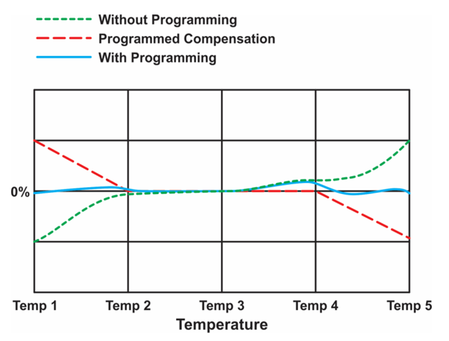
The accuracy of Allegro open-loop current sensor ICs is greatly enhanced with the addition of a digital temperature compensation algorithm that includes EEPROM technology. Piecewise linear
temperature compensation between five boundaries is employed to drastically reduce the native drift of the analog signal path without sacrificing the signal bandwidth. Figure 6 illustrates the
technique. Both the zero amp output voltage (QVO) and sensitivity can be adjusted with the algorithm. The native drift of either QVO or sensitivity is illustrated by the dotted line, the dashed
line shows the linear compensation that is added between the boundaries, and the solid line shows the resulting behavior of the sensor output. Notice in Figure 5 that the digital compensation
happens in parallel with the main signal path. This allows the analog output to remain at high speed while the gain and offset are compensated as the temperature changes slowly over time.
The compensation parameters are programmed at the Allegro factory end-of-line testing and are accomplished by integrating an EEPROM, a temperature sensor, and the digital piecewise linear
temperature compensation algorithm on the IC. This end-of-line programming provides a stable zero amp output voltage and sensitivity over the entire operating temperature range.
Sensor Performance
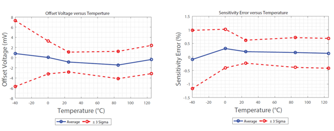
The results of the patented packaging techniques and the integrated digital compensation algorithm provide a sensor with near ±1% accuracy over the entire temperature range and operating
bandwidth of the sensor. These results can be seen in the graphs in Figure 7 below. The QVO (offset) error is less than ±8 mV (±0.5%) over the entire operating temperature range, and the
sensitivity is only ±1% over temperature.
Summary
By combining unique packaging techniques and advanced mixed signal semiconductor processes with advanced digital temperature compensation algorithms, an open-loop current sensor IC
achieves closed-loop accuracy. The small PCB footprint and the elimination of bulky and expensive ferromagnetic cores make these current sensor ICs from Allegro easy to integrate into applications needing high accuracy and speed, all at a price point below a closed-loop sensing solution.
For more information on current sensor ICs, including layout recommendations and other application notes, see the Hall-Effect Sensor IC Publications landing page: http://www.allegromicro.com/en/Design-Center/Technical-Documents/Hall-Effect-Sensor-IC-Publications.aspx
Additional application notes, frequently asked questions, and product information can also be found on the Allegro website at www.allegromicro.com.
Applicable Patents
1. Gagnon et al., “Current Sensor”, US Patent 7,166,807; filed June 3, 2005, and issued January 23, 2007; Assignee: Allegro MicroSystems, LLC.
2. Doogue et al., “Current Sensor”, US Patent 7,709,754; filed August 26, 2003, and issued May 4, 2010; Assignee: Allegro MicroSystems, LLC.
3. Milano et al., “Reinforced isolation for current sensor with magnetic field transducer”, US Patent 8,907,437; filed July 22, 2011, and issued December 9, 2014; Assignee: Allegro MicroSystems, LLC.
Originally published in EE Times China, April 2018. Reprinted with permission.
Copyright ©2018, Allegro MicroSystems, LLC
The information contained in this document does not constitute any representation, warranty, assurance, guaranty, or inducement by Allegro to the customer with respect to the subject matter of this document. The information being provided does not guarantee that a process based on this information will be reliable, or that Allegro has explored all of the possible failure modes. It is the customer’s responsibility to do sufficient qualification testing of the final product to insure that it is reliable and meets all design requirements.