Shifting the Offset Voltage of Current Sensors
By Alex Latham, Systems Engineer
Allegro MicroSystems, LLC
Most of the Allegro™ unidirectional current sensor ICs are trimmed such that the zero ampere output is at 0.1 × VCC . The advantage of having the output voltage at 0.1 × VCC is that the output can swing slightly lower than this value before saturating, allowing the user to measure zero ampere and slightly negative current. If Allegro were to attempt to trim the output to be zero volts at zero amperes, the output driver of the part would saturate above zero volts, deteriorating the ability to measure currents very close to zero amperes. This application note documents a simple operational amplifier circuit which can be used to subtract out the 0.1 × VCC offset of many of the Allegro current sensor ICs, as well as to shift the offset voltage to any required value.
Application Circuit
Figure 1 shows a simple differential op-amp circuit, which can be used to remove the offset from Allegro unidirectional current sensor ICs.
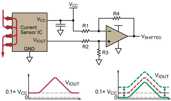
Figure 1. Current sensor with differential op-amp for removing the built-in offset of 0.1 × VCC . A summing amplifier can be used to increase the offset.
The resistors must be chosen such that:

This example shows how to subtract the built-in offset of 0.1 × VCC from the output of the IC. By choosing the correct resistor values, any fraction of VCC can be subtracted from the output of the IC.
The equation describing the differential op-amp circuit is:
![]()
Combining equations 1 and 2 means that:
![]()
and
![]()
Choosing values for R1 through R4 such that they satisfy equations 3 and 4 will result in the correct shift in the output of the sensor. Example values are:
• R1 = 100 kΩ
• R2 = 10 kΩ
• R3 = 100 kΩ
• R4 = 10 kΩ
While this circuit configuration will subtract the inherent offset of the sensor IC, the output voltage, VSHIFTED , will not be exactly zero volts at zero amps. This is due to the external op-amp saturating at some voltage higher than zero. Because of this, it is important to use an op-amp which is as close as possible to being a true rail-to-rail op-amp or supply it with a sufficient negative supply instead of ground.
These types of op-amps are readily available and provide much better rail-to-rail performance than the output of most of the Allegro sensor ICs. This is due to the output stage of the Allegro sensor ICs being optimized to provide a highly linear analog output, proportional to the sensed current, rather than rail-to-rail capability.
Lab Results
The circuit described above was used to shift the output of the ACS713-30A, so that it had no inherent offset voltage. The schematic is given in figure 2.
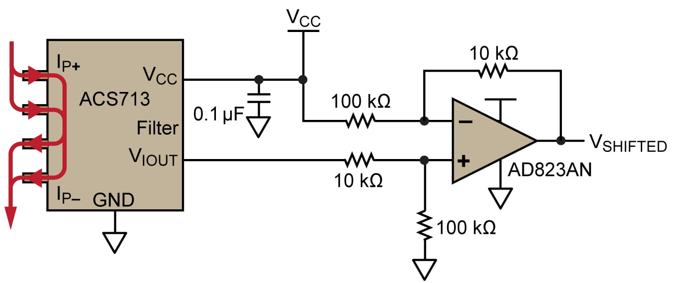
Figure 2. Schematic of ACS713 with output shifting circuit
A rail-to-rail op-amp, the AD823AN, was used in order to have the output of the circuit get as close to zero volts as possible at zero amperes. Figure 3 shows a scope trace of the shift circuit working as intended, and figure 4 shows a zoomed in-view of figure 3, highlighting the saturation of the output of the shift circuit. The op-amp is only able to get down to approximately 30 mV. As the sensitivity of the ACS713-30A is 133 mV/A, this corresponds to about 225 mA, which is very close to the current level at which the shifted output saturates, showing the expected behavior.
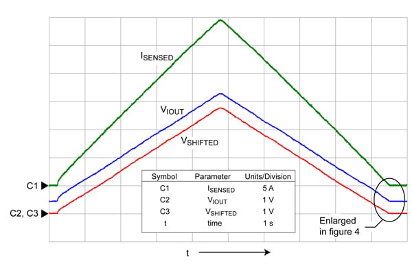
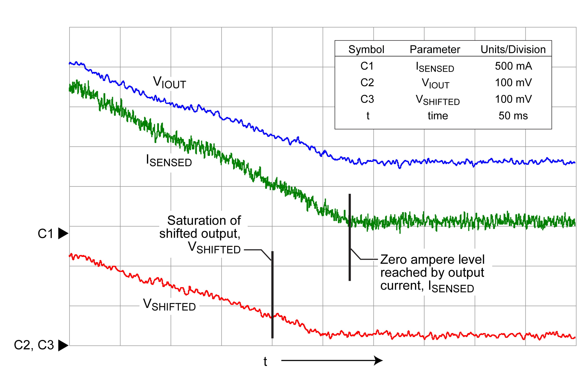
Figure 4. Zoomed-in view from figure 3. Note that the output of the shift circuit, VSHIFTED , saturates before the current, ISENSED , gets to zero.
Copyright ©2012-2013, Allegro MicroSystems, LLC
The information contained in this document does not constitute any representation, warranty, assurance, guaranty, or inducement by Allegro to the customer with respect to the subject matter of this document. The information being provided does not guarantee that a process based on this information will be reliable, or that Allegro has explored all of the possible failure modes. It is the customer’s responsibility to do sufficient qualification testing of the final product to insure that it is reliable and meets all design requirements.
Reference: AN296092-AN