Overcoming Battery Cooling Challenges to Enable Safe and Reliable Electric Two-Wheelers
Introduction
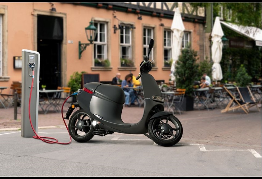
The rise in popularity of electric bikes and two-wheelers has brought to focus the need for increased safety requirements with these vehicles. Lithium-ion (Li-ion) batteries are the most commonly used sources of power, but they come with critical cooling requirements to ensure vehicle safety. This article discusses options available in battery technology, commonly used battery cooling methods, requirements and challenges associated with cooling methods, and motor drivers that overcome these challenges.
Background
The choice of battery greatly affects the design of an electric two-wheeler (E2W). Lithium-iron-phosphate (LiFePO4) batteries provide a stable chemical and thermal chemistry, better safety (no thermal runaway), and lower manufacturing cost compared to Li-ion batteries. The energy density (Wh/kg) in Li-ion batteries, however, is higher than in LiFePO4 batteries, which encourages use of Li-ion batteries in size- and weight-constrained applications, such as electric vehicles. While an E2W battery typically employs a cooling method, use of a Li-ion battery requires more thermal management than most because the higher discharge rate of Li-ion necessitates more cooling than other battery technologies. This emphasizes the need for reliable, high-performance cooling systems.
Battery Cooling Methods
Heat generated across a battery pack is directly proportional to the discharge rate of the battery. Batteries are manufactured to work within a specific temperature range. For safe operation, a cooling system must maintain external battery-pack temperature at approximately 20˚C to 40˚C and a maximum internal temperature variation of no more than 5˚C. Various cooling methods are available, including fin, air, and liquid cooling.
Cooling Fins
Cooling fins work on the principle of higher power dissipation through higher surface area to increase the rate of heat transfer. The heat transfer process occurs simultaneously from battery pack to fin (conduction) and from fin to air (convection). However, as the surface area of the fins increases, the weight of the fins also increases. As a result, fins are widely used in lower-power electronics components, but they can become impractical for battery-cooling applications.
Air Cooling
In the air-cooling method, the battery-to-air heat transfer occurs through convection. As air runs over the surface, heat emitted by the battery pack is carried away from it. Although air cooling is simple and easy, it is not very efficient, and it is relatively crude compared to liquid cooling. However, air cooling is preferred when feasible because it is relatively simple to implement, such as in lower-powered electric vehicles—specifically, two-wheelers.
Liquid Cooling
Liquids have higher heat conductivity and capacity than air, which makes liquid cooling more efficient. Liquid cooling can be indirect or direct: Indirect liquid cooling uses a system of pipes to circulate a high-heat-capacity coolant, whereas direct cooling submerges the entire battery in a very-low-conductivity coolant.
Summary of Cooling Methods
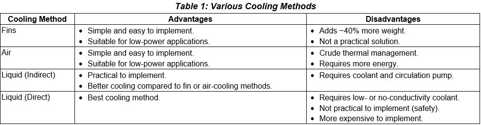
The advantages and disadvantages of each cooling method are summarized in Table 1. Although direct cooling achieves the best cooling performance, vehicle safety concerns have prevented adoption in application. Thus, practicability has made indirect cooling the most acceptable liquid-cooling solution. Air cooling requires a high-speed fan that implements air circulation. Indirect cooling requires a coolant pump driven by a high-speed motor with additional cooling fans (optional) for the cooling mechanism.
Driving Fans and Pumps in Battery-Cooling Systems
Practical battery-cooling solutions require motors to drive fans or pumps that deliver air or liquid for cooling. The performance of a motor driver for this application is characterized by noise, efficiency, and startup speed. Brushless DC (BLDC) motors are generally preferred for their high efficiency, high power density, low maintenance requirements, long lifespan, and wide range of speed controls. Performance, reliability, and cost factors must be weighed when choosing a BLDC motor.
For example, during cold-startup, the thermal management of the battery is critical due to higher thermal resistance, which demands fast-startup motor drivers. The performance achieved by many commutation algorithms must also be weighed to ensure the desired response speed, power, noise, and efficiency are met at all stages of operation. Protection features must also be included in the motor drivers and gate controller to protect the motor and driver/controller in the event of a fault.
The noise performance of the motor depends greatly on the commutation technique: Although trapezoidal can provide greater efficiency at high speed, sinusoidal is often preferred for its superior noise performance, while field-oriented control (FOC) algorithms are the fastest and most-accurate method. FOC algorithms provide a unity power factor for high-efficiency and low-noise operation.
The overall cost and size of a system depends greatly on the number of external passive components required for the motor driver operation. Many implementations of motor drivers require the addition of an external capacitor, which creates electromagnetic interference (EMI) in the form of high-frequency-switching noise. Mitigating the EMI can require additional components and thermal management, as well as corresponding development time and cost.
Fast, High Efficiency, Reliable Motor Drivers
Purpose-Built Algorithms Deliver Smooth, Fastest Response
Devices from Allegro MicroSystems include many proprietary algorithms purpose-built for fast, reliable operation of electric two-wheelers. These include:
- Sensorless-startup algorithms, which can drive a BLDC motor from startup to full speed in typically 50 ms. This ensures the fan (air cooling) or pump (indirect liquid cooling) starts quickly and receives the necessary cooling during the cold-crank scenario.
- Two-pulse initial position detection (IPD), which provides the fastest, most-accurate method for reliable start-up of the BLDC motor in sensorless operation. The IPD algorithm ensures reliable and accurate initial position detection, requires less resolution (30 degrees) and less detection time than other startup methods, and assists in reducing the overall startup time of the BLDC motor.
- FOC algorithm, which ensures a unity power factor to achieve the highest motor efficiency and low-noise operation. Closed-loop speed control housed in the controller ensures operation at a steady speed despite any voltage variations in the load or line. The FOC algorithm is included in the QuietMotion family of high-efficiency, low-noise controllers (integrated gate drivers) and motor drivers from Allegro.
Minimal Requirements for Additional Components Deliver Cost Savings and Reliability
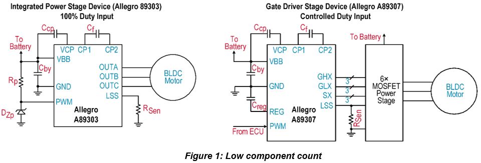
Motor driver solutions for battery-cooling fans and pumps are available with integrated control including options for an integrated power stage or a gate driver stage. Components needed for full-speed operation can be very minimal, as shown for two example Allegro devices in Figure 1:
- A89303, a three-phase sensorless pump driver for integrated motor drivers with ultra-fast startup, which includes sensorless-startup and two-pulse IPD algorithms. As shown, it can be driven at full speed with 100% duty input on the pulse-width modulation (PWM) pin.
- A89307, an automotive FOC BLDC motor controller for high-power applications, which integrates code-free algorithms and application-specific parameters—such as rated speed, current, speed profile, and resistance, among others.
Tuning these motor controllers is very easy and can be quickly adapted, thus reducing development time and cost.
Most devices from Allegro also house the capacitor of the internal regulator, which bypasses the high-frequency switching noise of the internal digital circuitry. A spread-spectrum clock feature further helps to spread the emission. These features allow the customer to reduce the development time needed to achieve compliance with electromagnetic-compatibility (EMC) standards with minimal additional components.
To protect the device and connected systems in the event of a fault, protection features included in Allegro devices include current limit, overcurrent protection/drain-to-source (VDS) sensing, programmable safe braking thresholds, undervoltage lockout, overvoltage protection, lock detection, open phase protection, vibration lock detection, overspeed protection, and thermal shutdown.
Allegro Motor Driver Portfolio for Battery Cooling Fans
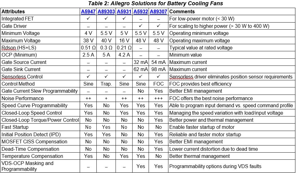
A wide range of solutions from Allegro can fit in multiple customer requirements for electric vehicle battery cooling applications. Various offerings from Allegro are compared in Table 2. Devices with an integrated power stage (A5947, A89303, A5931) are capable of handling typical motor power up to ~30 W, whereas gate drivers (A5932, A89307) can be used to drive external metal-oxide-semiconductor field-effect transistors (MOSFETs) supporting power up to ~400 W, depending on gate current strength. Integrated gate controllers offer the built-in FOC control algorithm (A89307), which has an edge over sinusoidal control on efficiency and noise performance.
Based on the article, "Overcoming Battery Cooling Challenges to Enable Sage and Reliable Electric Two-Wheelers" by Vashist Bist and Shashank Wekhande, republished with permission. For portions not copyrighted by original publisher, Copyright ©2023, Allegro MicroSystems, Inc.
Copyright 2023, Allegro Microsystems.
The information contained in this document does not constitute any representation, warranty, assurance, guaranty, or inducement by Allegro to the customer with respect to the subject matter of this document. The information being provided does not guarantee that a process based on this information will be reliable, or that Allegro has explored all of the possible failure modes. It is the customer's responsibility to do sufficient qualification testing of the final product to ensure that it is reliable and meets all design requirements.
Copies of this document are considered uncontrolled documents.