Current Sensor Accuracy Fundamentals: Understanding Sensitivity and Offset Error

Introduction
In modern power electronics, from EV traction inverters and onboard chargers to industrial motor drives and high-efficiency solar inverters, the accuracy of current measurement directly determines the performance, efficiency, and safety of the entire system. Yet “accuracy” is rarely a single number; it is the culmination of multiple error sources, each with its own physical origin and its own dependence on operating conditions.
Among all of these error sources, two stand above the rest as the foundational pillars of current sensor accuracy: Sensitivity Error and Offset Error/Quiescent Voltage Output Error (QVO Error). Together, these two errors define the sensor’s transfer function and they dominate the total error budget across the entire measurement range. Every other error source (temperature drift, stray fields, mechanical stress, lifetime aging) ultimately manifests as a disturbance of one of these two parameters.
In the Allegro current sensor portfolio, the offset error specification reflects the small, unwanted deviation in the sensor’s output when zero primary current is applied. However, the way this offset is defined and measured depends on whether the device is single-ended output or a differential (referenced) output part.
For single-ended current sensors (meaning the sensor has one single analog output voltage signal pin, VOUT, that is referenced to the device ground pin, GND), offset error is defined as the deviation of the Quiescent Voltage Output (QVO) from its ideal value, since the output is referenced to GND. For differential sensors (devices that feature VREF), such as the ACS37030, offset error is instead defined as the difference (QVO – VREF), reflecting that the output is intended to be read differentially against the device’s own reference allowing for a much tighter offset specification because QVO and VREF are designed to track each other over temperature, supply variation, and lifetime drift.
This application information is dedicated to deconstructing current sensor accuracy. Here, the focus is exclusively on Sensitivity and Offset Error: what they are, where they come from, how they interact, and when each dominates.
Accuracy
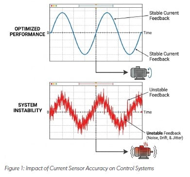
Accuracy is an important consideration when selecting a current sensor, influencing the reliability, efficiency, and safety of a wide range of applications. The accuracy of a current sensor refers to its ability to measure the true value of the current flowing through a conductor, with minimal deviation from this expected value. Understanding and carefully considering accuracy is crucial because it directly impacts the performance and effectiveness of the systems that rely on this measurement. Figure 1 illustrates the link between component-level sensor parameters and system level performance, showing the divergence of the ideal transfer function caused by unmitigated sensitivity and offset errors and the resulting instability in a motor control application. This composite visualization highlights the impact of current sensor accuracy on control systems, contrasting optimized performance with the system instability.
Why Does Accuracy Matter?
Many applications, such as motor control, power supply regulation, and battery management, rely on accurate current measurements for precise control. In motor control, for instance, accurate current feedback is essential for achieving the desired torque and speed. Deviations from the target current can lead to suboptimal performance, instability, or even damage to the motor.
In power supplies, precise current sensing is needed to regulate the output voltage and current. Inaccurate current measurements can result in poor load regulation, false overcurrent trips, or inefficient operation. Accurate current sensing enables efficient operation by minimizing losses and optimizing system performance. For example, in solar inverters, precise current measurements are needed to maximize the power extracted from the solar panels. Inaccurate measurements can lead to suboptimal maximum power point tracking (MPPT) and reduced energy harvest.
In electric vehicle (EV) charging systems, accurate current sensing is essential for controlling the charging rate and ensuring efficient energy transfer. Inaccurate measurements can result in slower charging times, increased energy losses, or even safety hazards. Accurate current sensing is critical for detecting fault conditions, such as overcurrents and short circuits, and for implementing effective protection mechanisms. Inaccurate measurements can lead to false alarms or, more critically, to a failure to detect a fault, resulting in damage to the equipment or even safety risks.
For instance, in power supply applications, accurate current sensing is needed to trigger overcurrent protection mechanisms. If the current sensor underestimates the actual current, the protection circuitry may fail to activate in time, leading to component failure or fire hazards. Systems that rely on accurate current measurements tend to be more reliable and have a longer lifespan. This is because precise control and efficient operation reduce stress on components, minimizing wear and tear. Inaccurate measurements, on the other hand, can lead to overheating, overstress, and premature failure of components.
For example, in industrial motor drives, accurate current sensing ensures that the motor operates within its safe operating area, preventing overheating and extending its lifespan. The required accuracy level depends on the specific application and its performance requirements. In some applications, such as simple overcurrent protection, a moderate accuracy level may be sufficient. In other applications, such as precision motor control or high-end power supplies, a high accuracy level may be necessary.
While high accuracy is often desirable in current sensing applications, it’s not always necessary or cost-effective. By carefully analyzing the system’s requirements and considering the potential impact of measurement errors, engineers can make informed decisions about the appropriate accuracy level for their specific needs while reducing overall system costs.
The accuracy required at low currents is often very different from the accuracy required at high currents. A battery management system measuring 100 mA standby current has very different needs than the same system measuring a 400 A discharge event.
The Anatomy of a Current Sensor Transfer Function
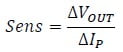
Before diving into individual error sources, it is essential to understand what the sensor is fundamentally doing. A linear analog current sensor implements the following ideal transfer function:
VOUT = (Sens * Ip) + Vqvo
Equation 1: Sensor output transfer function equation
Where:
VOUT is the sensor’s analog output voltage. Sens is the sensitivity (mV/A), the slope of the transfer function. IP is the primary current flowing through the sensor. VQVO is the Quiescent Voltage Output, the Y-intercept of the transfer function (the output when IP = 0 A).
This is the equation of a straight line, y = m x + b. Error in a current sensor can be understood as a deviation from this ideal line. Sensitivity Error is the deviation from the slope of the best fit line of the measured output to the ideal sensitivity, while Offset Error is the difference between measured IP = 0 and the ideal QVO.
The Role of Chopper Stabilization in Maintaining Accuracy
Modern Hall-effect current sensors face an inherent challenge: the Hall element itself produces a small DC offset voltage caused by manufacturing asymmetries in the Hall plate geometry, piezoresistive effects from packaging stress, and doping variations in the silicon. Left uncorrected, this offset would drift significantly with temperature and time, degrading the accuracy parameters discussed above. To overcome this, many Allegro current sensors employ chopper stabilization: a dynamic offset cancellation technique that periodically reverses the bias current direction through the Hall plate at a high frequency. The magnetic signal modulates with this chopping action, while the unwanted DC offset and low frequency (“1/f”) noise remain stationary. After demodulation and low-pass filtering, the offset and flicker noise are effectively removed from the signal path.
A slope error has zero impact at IP = 0 but grows linearly with current. An offset error is constant across all currents, meaning its relative impact is large at low currents and much smaller at high currents.
What are the Main Individual Components of Current Sensor Accuracy?
Accuracy is a comprehensive measure that encompasses several individual error components including:
Sensitivity and Sensitivity Error
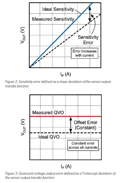
Sensitivity is the magnitude of the sensor’s output signal for a given input current. It is a relationship between the change in the output of the sensor per unit change in the measured current or field, and it is typically expressed in mV/A or mV/G. Sensitivity is the sensor’s ability to detect small changes in current, and the deviation of the sensor’s actual sensitivity from its nominal or ideal value is sensitivity error.
Equation 2: Sensitivity formula where Sens is sensitivity, ΔVOUT is the change in output voltage, and ΔIP is the change in measured primary current.
Sensitivity error becomes more significant at higher current levels. It is a proportional error, meaning it scales with the magnitude of the measured current. For example, if a sensor has a sensitivity error of ±1%, this error will result in a 10 mA error when measuring a 1 A current and a 100 mA error when measuring a 10 A current.
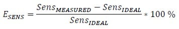
Equation 3: Sensitivity error formula where SensMEASURED is the actual sensitivity measured and SensIDEAL is the sensitivity target specified in the datasheet.
A higher sensitivity means a larger output signal for the same current, which can be advantageous in many applications. A larger output signal makes it easier to process and interpret the signal, especially in noisy environments. A sensor with high sensitivity can provide a stronger signal for low-current measurements, improving the signal-to-noise ratio (SNR). A higher sensitivity improves the SNR by producing a stronger signal relative to the noise floor. This is crucial for accurate measurements, especially in electrically noisy environments; sensors with high sensitivity provide better immunity to noise, allowing for more reliable current measurements in challenging conditions.
Additionally, sensitivity must be considered in relation to the desired measurement range. A sensor with very high sensitivity might saturate (reach its maximum output limit) at relatively low currents, which limits the measurable range. Choosing the right sensitivity ensures the sensor operates within its linear region for the entire range of currents expected in the application and provides adequate signal strength without saturating at the maximum expected current levels.
The sensitivity of the current sensor must be compatible with the input range and resolution of the downstream signal processing circuitry, such as an analog-to-digital converter (ADC) or a microcontroller. The output voltage range produced by the sensor should match the input voltage range of the ADC to maximize the use of the ADC’s dynamic range.
Some current sensors, like the ACS70310, ACS37600, and ACS37610, offer customer-programmable sensitivity, allowing designers to optimize the sensor’s performance for their specific application requirements. Adjustable sensitivity provides flexibility to fine-tune the sensor’s output characteristics and compensate for variations in the application environment.
Different applications have different sensitivity requirements. For example, high-precision current sensing in automotive applications (EVs, BMS, traction inverters) may require sensors with very high sensitivity to detect minute current changes accurately. In contrast, industrial motor control applications may require sensors with moderate sensitivity and a wide measurement range to handle both normal operating currents and fault currents. To choose a current sensor based on system sensitivity, consider both the maximum current needed to measure and what resolution is required at the low end to measure accurately.
For example, a 50 A sensor with 40 mV/A sensitivity will output 2 V at max scale. For a 12 bit ADC (4096 steps) at 5 V, the resolution is about 1.22 mV. Therefore, the current resolution = 1.22 mV / (40 mV/A) or 30.5 mA/bit. This assumes the ADC reference is 5 V and the sensor output spans the full ADC range. If the system required 10 mA resolution, then a higher sensitivity sensor or a higher resolution ADC would be required to sufficiently meet the requirements of the application.
As another example, a system designer is using the ACS37032LLZATR-065B3, with a specified sensitivity of 20.3 mV/A and a maximum sensitivity error of ±2%. The sensor is measuring a 60 A load. To calculate the error induced by a potential worst case 2% sensitivity error, multiply 60 A x 2% = 1.2 A. If the applied current was only 20 A, the error would then be 0.4 A. This illustrates that sensitivity error is less critical at low currents compared to Offset Error.
Quiescent Voltage Output (QVO) and Offset Error (or QVO Error)
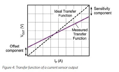
Offset error (also referred to as Quiescent Voltage Output error for some products) is the output of the sensor when the input current is zero and no current is flowing through the sensor. It represents the deviation from the ideal quiescent voltage output. While Sensitivity Error is proportional to the signal, Offset Error is an additive error that is most critical at low current levels.
EQVO = VQVO MEASURED - VQVO IDEAL
Equation 4: Quiescent voltage output error formula
Offset error affects the accuracy of low-current measurements. Even small offsets can cause significant errors when measuring small currents. It introduces a constant error across the entire measurement range, but its relative impact decreases as the current level increases.
Single-Ended Parts
On a single-ended current sensor, the analog output pin (VOUT) is referenced to the device’s own ground (GND). When zero current flows through the primary conductor, the output sits at the Quiescent Voltage Output (QVO), which is typically VDD/2 for bidirectional parts (e.g., 1.65 V on a 3.3 V supply, or 2.5 V on a 5 V supply) or VDD/10 for unidirectional parts. The “offset error” in this case is simply the deviation of the actual measured QVO from its ideal nominal value:
VOE = VQVO MEASURED - V QVO IDEAL
Equation 5: Offset error is identical to the quiescent voltage output error on single ended parts.
Because there is no separate reference pin, the downstream ADC or circuit interprets the output relative to a fixed rail (GND or a system reference), so any drift in QVO directly translates into a current measurement error.
Differential/Referenced Parts
On devices that include a dedicated VREF output pin (like the ACS37030), the sensor is designed to be read differentially. The downstream ADC measures the difference (VOUT − VREF) rather than VOUT referenced to ground. In this architecture, both QVO and VREF are nominally set to the same value (e.g., 1.65 V on the ACS37030 bidirectional variants), and the true zero-current output is the difference between them:
VOE = VQVO MEASURED - VREF
Equation 6: Offset error is the difference between the quiescent voltage output and the reference voltage output for differential devices
QVO and VREF are generated from the same internal reference circuitry and are designed to track each other closely over temperature, supply voltage, and other operating conditions. This means that even if both pins drift by, for example 8 mV due to temperature, the differential offset (QVO – VREF) remains very small allowing for tighter offset error specifications, separate from the individual VQVO_E and VREF_E specs which can each independently drift by ±10 mV, for example.
The differential measurement architecture employed in devices like the ACS37030 changes how offset error propagates through the sensor. Because QVO and VREF are generated from the same internal network, common-mode disturbances, including supply ripple, temperature drift, and even long-term aging, affect both pins nearly identically and are subtracted out at the differential ADC input.
Ratiometric vs. Non-Ratiometric Architecture
An important architectural distinction in the Allegro current sensor portfolio is between ratiometric and non-ratiometric output sensors. In ratiometric devices (ACS724), both sensitivity and QVO scale proportionally with the supply voltage (VDD), allowing system-level cancellation of supply variation when the downstream ADC reference is tied to the same rail. In non-ratiometric devices (such as the ACS37010), an internal voltage reference holds the output stable regardless of VDD fluctuations, providing higher accuracy at the cost of slightly higher complexity. Designers should select the architecture that best matches their ADC reference scheme.
Conclusion
Achieving high accuracy in a current sensing application is a systematic process of identifying, quantifying, and mitigating multiple sources of error. As deconstructed in this note, Sensitivity Error and Offset Error/QVO Error form the two foundational pillars of sensor accuracy. Sensitivity Error scales proportionally with current and dominates at the high end of the measurement range, while Offset Error remains constant and dominates at the low end. Understanding this asymmetry empowers engineers to perform meaningful error budget analyses, select the right sensor for the right job, and apply targeted system-level mitigations such as zero-current calibration, temperature compensation, and differential signal chain design using sensors with the VREF feature.
This note focused exclusively on the static, room-temperature behavior of these two parameters. Subsequent application notes in this series will address how external influences, operating temperature, stray magnetic fields, mechanical packaging stress, and lifetime aging disturb these foundational parameters. Following that, the series will explore dynamic performance (bandwidth, phase shift, response time, CMTI) and conclude with isolation and high-voltage robustness, providing a complete reference for designing reliable, high accuracy current sensing solutions.
This document is part of a comprehensive series that provides guidance about current sensor selection. For additional content in this series, refer to Beyond the Datasheet: Mastering Current Sensing Selection.