Hall-Based BLDC Gate Drive Saves Microprocessor IO and Provides Zero Speed Torque
.jpg?h=320&iar=0&mh=320&mw=640&w=427&sc_lang=ja-jp&hash=8D7276B81A71F0B0D4EABBE9CB5BD74E)
SENSORS IN BLDC MOTORS
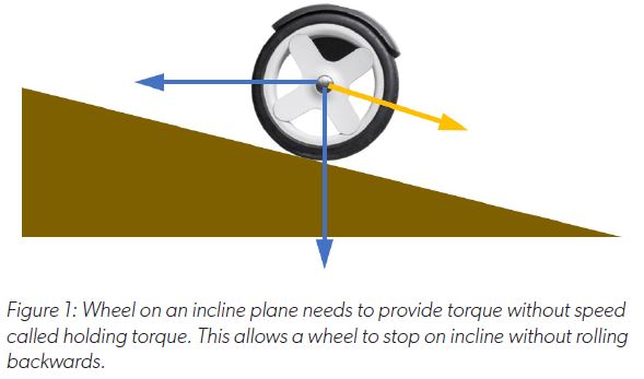
Many BLDC motor applications require Hall-based position sensing to accommodate direction changes quickly and provide holding torque. For example, a robotic lawnmower, ebike, or personal mobility device must be able to stop on an incline but must not roll backwards. Another example is a system that requires direction change quickly, such as reciprocating or oscillating machinery. And finally, balance boards, single wheel personal mobility scooters, and hover boards require dynamic fast response and ability to provide torque in either direction quickly to maintain balance. Since BLDC motors do not self-commutate, the motor requires sensors to identify the rotor position. Sensorless solutions that can achieve these requirements are complicated systems to design and often require motors that maintain a high saliency. In many cases, the investment required to go to a sensorless solution drives many customers to consider the sensored approach.

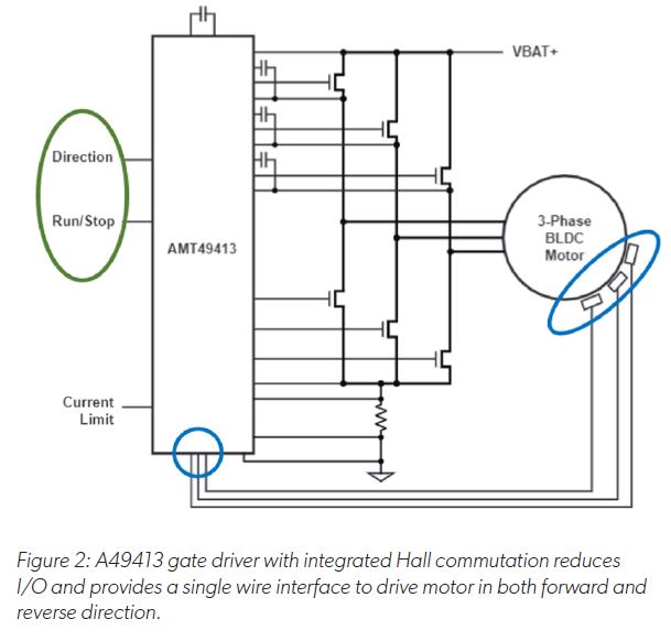
Allegro gate driver ICs with integrated Hall commutation are designed with the Hall-based commutation engine integrated into the IC. Hall signals go directly into the IC, saving 3 to 6 I/O on microprocessor. By integrating the commutation into the gate driver, the microcontroller only needs to provide PWM signal to control speed.
A SIMPLE SOLUTION FOR A COMPLICATED PROBLEM
By integrating the commutation logic and the sensor inputs into the gate driver, the microprocessor can provide a single PWM signal to move the motor in the forward or reverse direction by only changing the duty cycle of the PWM.
By applying PWM to the direction pin, the controller can provide torque in either forward or reverse direction, and by quickly changing between the two directions, the resultant force can create a balance where the speed is zero. On a flat surface with no external force applied, this corresponds to a 50% duty cycle. A duty applied that is greater than 50% will provide torque in one direction, where duty cycles less than 50% will provide torque in the other direction.

For oscillating and reciprocating systems, the A49413 can be used in a different way. PWM is applied to enable input that will control the speed by applying an average voltage to the winding, and the direction pin can be used to change direction quickly.
FEATURES FOR A COMPLETE SYSTEM
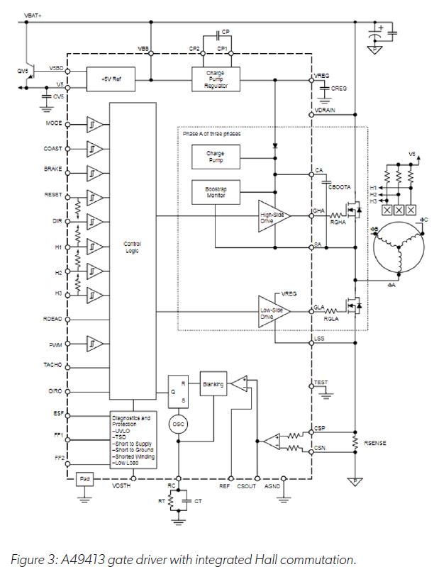
The A49413 integrates additional features that enable a fully functioning system with current control, speed feedback, and LDO regulator.

A tach output provides commutation speed to the microprocessor to simplify closed loop speed control.
An integrated current sense amplifier with adjustable gain and offset automatically limits the current to the motor with fixedofftime PWM current limit that can protect the system from overheating. The current sense amplifier output is available so an external microprocessor can implement a current control or torque control loop or monitor current for environmental conditions such as increased load or stall.
The integrated LDO controller can be used to provide Hall sensor, angle sensor, and microprocessor supply, reducing external components and reducing footprint. Integrated fault reporting is provided that includes thermal shutdown, MOSFET short-circuit detection, and under voltage conditions.
A SYSTEM SOLUTION WITH ALLEGRO’S GATE DRIVERS, HALL SENSORS, AND ANGLE SENSORS
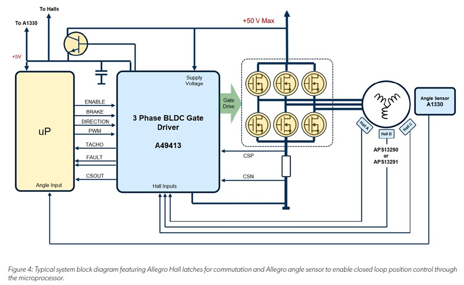
Allegro Hall latches provide precision switch points in a rugged package. Output is completely compatible with A49413 inputs and requires only a single pull-up. 5 V can be supplied directly to the latch from the integrated LDO controller in the A49413.
Allegro’s 360-degree angle sensors based on circular vertical Hall (CVH) technology can provide position information to the microprocessor for closed loop position control.
A typical implementation is shown in figure 4. The system-level components show the A49413 with LDO controller supplying the microprocessor, Hall latches, and angle sensor. Speed and current information are supplied back to the microprocessor for control loop inputs. The angle sensor can be used to obtain rotation angle for closed loop position control.
For other Allegro motor drivers that offer integrated Hall commutation, consider the A4915 for systems that do not require a current sense amplifier and the A4931 for systems with loads less than 400W.

Copyright 2022, Allegro MicroSystems.
Based on the article, "Hall-Based BLDC Gate Drive Saves Microprocessor IO" by Dan Jacques, originally published in GlobalSpec. Republished with permission. For portions not copyrighted by original publisher, Copyright ©2023, Allegro MicroSystems, Inc.
The information contained in this document does not constitute any representation, warranty, assurance, guaranty, or inducement by Allegro to the customer with respect to the subject matter of this document. The information being provided does not guarantee that a process based on this information will be reliable, or that Allegro has explored all of the possible failure modes. It is the customer's responsibility to do sufficient qualification testing of the final product to ensure that it is reliable and meets all design requirements.
Copies of this document are considered uncontrolled documents.