
Overcoming the DC Protection Challenge with Solid-State Circuit Breakers

The DC Interruption Challenge
As electrification and decarbonization accelerate, direct current (DC) architectures are replacing alternating current (AC) distribution in critical applications. Solar photovoltaic (PV), battery energy storage systems (ESS), and electric vehicle charging infrastructure (EVCI) are inherently DC, and hyperscale data centers are adopting high-voltage DC buses to eliminate redundant AC-to-DC conversion stages and improve power density and efficiency.
As DC bus voltages climb to 800 V and beyond, safely interrupting fault currents has become a pressing engineering challenge. Protecting a DC bus is fundamentally harder than protecting a traditional AC system, for two reasons:
- Absence of a Natural Zero-Crossing: AC current crosses zero every half cycle, naturally extinguishing any arc that forms as breaker contacts open. DC has no zero-crossing, so the arc persists across the gap, eroding contacts and risking thermal runaway, fire, or explosion.
- Extreme Fault Current Slew Rates (di/dt): Low-inductance, high-capacitance DC power stages let short-circuit currents reach destructive peaks within microseconds, far faster than physical contacts can separate.
Comparing DC Circuit Protection Technologies: Mechanical, Pyrofuses, and SSCBs
Engineers protecting high-power DC systems typically evaluate three technologies: electromechanical breakers and contactors, pyrotechnic fuses (pyrofuses), and solid-state circuit breakers (SSCBs). Each trades off response speed, conduction efficiency, serviceability, and lifecycle cost, as summarized in Table 1.
Electromechanical Breakers and Contactors
Mechanical breakers and contactors open physical contacts, offering negligible conduction loss and true galvanic isolation. But moving physical mass is slow: on ESS or EV fast-charging buses where fault currents rise at several hundred A/μs, current reaches destructive peaks before the contacts separate. The resulting DC arc requires arc chutes or magnetic blowouts and erodes the contacts, limiting fault life and requiring regular maintenance.
Pyrotechnic Disconnects (Pyrofuses)
A pyrofuse fires a pyrotechnic charge to sever a copper busbar, clearing faults much faster than a mechanical breaker with similarly low conduction loss. However, pyrofuses are single-use: every trip requires physical replacement. That is acceptable for crash disconnection in passenger EVs but costly for remote solar farms, utility-scale ESS, and data centers, where nuisance trips and transient faults cause downtime and service calls.
Solid-State Circuit Breakers (SSCBs)
SSCBs replace moving contacts with power semiconductors, increasingly silicon carbide (SiC) MOSFETs or gallium nitride (GaN) FETs. With high-bandwidth current sensing and fast isolated gate drivers, an SSCB interrupts a short circuit thousands of times faster than a mechanical breaker, with no arc and no contact wear, clamping fault currents long before they peak. The trade-offs are conduction loss through the devices’ on-state resistance (Ploss= I2 × RDS(on)), which demands careful thermal design, and off-state leakage, which means designs that must meet galvanic-isolation requirements add a series no-load mechanical isolator.
Summary Comparison of DC Protection Technologies
| Performance Metric | Electromechanical Breaker | Pyrotechnic Fuse (Pyrofuse) | Solid-State Circuit Breaker (SSCB) |
|---|---|---|---|
| Typical Response Time | 10 ms to 50+ ms | 0.5 ms to 2 ms | <1 µs to 5 µs |
| Arcing During Interruption | Severe (requires arc chutes/blowouts) | Contained internal blast/arc | None (completely arc-free) |
| Peak Let-Through Energy (I2t) | Very High | Low to Moderate | Ultra-Low (clamps fault early) |
| Typical On-State Resistance | µΩ | µΩ | mΩ |
| Reset Ability & Endurance | Resettable; limited fault life (103–104 cycles) | Single-use (sacrificial; requires replacement) | Fully resettable (remote/software); >106 cycles |
| Galvanic Isolation | Yes (physical air gap) | Yes (severed conductor) | No (requires series no-load mechanical isolator) |
| Smart Features & Diagnostics | Minimal (basic auxiliary contacts) | None (requires external trigger circuit) | Advanced (programmable trip curves, soft-start, telemetry) |
Table 1: Comparison of DC circuit protection technologies.
Inside the Solid-State Circuit Breaker: Architecture and Operation
To interrupt faults in microseconds without arcing, an SSCB operates as a tightly synchronized, closed-loop system that integrates high-speed sensing, isolated gate control, and fast SiC power switches.
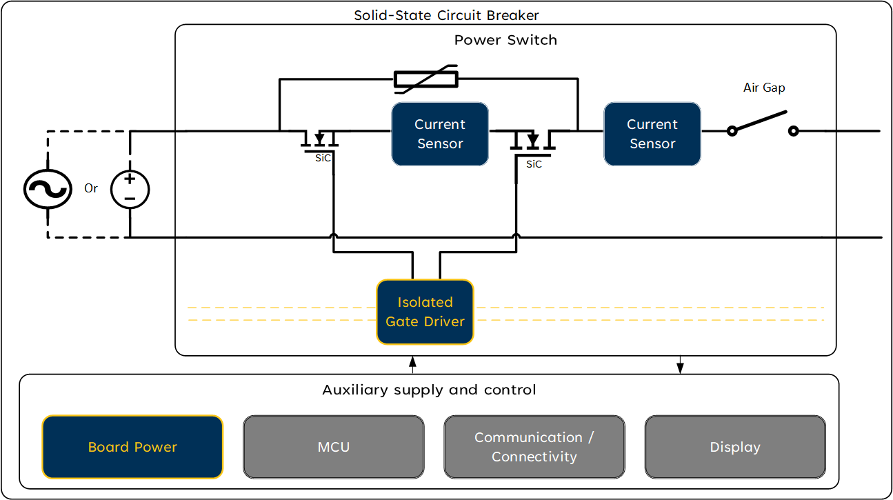
Figure 1: Block diagram of a solid-state circuit breaker (SSCB) for data center DC power distribution.
As Figure 1 shows, a reinforced isolation barrier separates the high-voltage power path from the low-voltage control electronics. This isolation is essential: the SiC switches sit at bus potentials of 800 V or higher and swing by hundreds of volts within nanoseconds during fault turn-off. Without a reinforced barrier, a bus fault could propagate into the control circuitry and endanger equipment and personnel, and switching transients could corrupt the gate and sensing signals the breaker depends on. Every gate command, bias supply, and measurement that links the two sides must therefore cross that barrier through an isolated channel.
The breaker’s key building blocks are:
- Bidirectional SiC Power Switches: SiC MOSFETs are arranged back-to-back (typically common-source, which lets both gates share the same reference). Because each MOSFET’s body diode conducts in reverse, two devices are needed to block current in both directions. Commonly, multiple switches are connected in parallel to minimize R_(DS(on)).
- Current Sensors (Mid-Switch and Output Placement): Sensors sit either between the back-to-back switches, referencing the local source potential, or at the output before the air gap, monitoring total line current. They provide telemetry for both thermal overload (I²t) and instantaneous short-circuit detection.
- Voltage Clamping Network (MOV / TVS): When the MOSFETs turn off thousands of amperes in under a microsecond, loop inductance generates a large voltage spike (V=L_loop×di⁄dt). A metal oxide varistor (MOV), transient voltage suppressor (TVS), or RC snubber across the switch clamps this spike below the MOSFET breakdown rating and absorbs the residual line energy.
- Series Mechanical Air Gap: Because of semiconductor leakage, the switches alone may not meet galvanic-isolation requirements of applicable standards (such as UL 489I), so a no-load mechanical switch is placed in series. It opens at zero current after the SiC stage clears the fault, providing physical isolation without arcing.
- Isolated Gate Driver: Delivers the high peak source and sink currents needed to rapidly switch large paralleled SiC arrays, while shielding the control system from the high-power side.
- Isolated Bias Supply: Typically, a separate isolated DC/DC supply is needed to power the gate drive of the FETs. However, Allegro MicroSystems’ integrated Power-Thru™ technology eliminates this supply by delivering gate-drive power across the same isolation barrier as the control signal.
Rapid Response to a Current Fault Condition
In a DC SSCB, protection can be no faster than the current sensor. On the low-inductance buses found in ESS, EV fast chargers, and 800 V data center racks, short-circuit current rises at several hundred A/μs. Because total clearing time is the sum of sensor delay, controller processing, and gate-driver turn-off, a <1 μs to 2 μs trip budget leaves only 100 ns to 300 ns for current detection.
Allegro’s CT456 is built to meet that timing budget directly on the busbars and high-current PCB traces these systems use, measuring currents into the kiloampere range. Its key advantages are:
- Contactless, Coreless TMR Sensing: This tunnel magnetoresistance (TMR) sensor mounts above or inside a slotted busbar or high-current PCB trace. Because current never enters the IC, it adds no insertion loss and scales easily to the clearance and creepage needs of a high-voltage bus.
- DC to 1 MHz Bandwidth & 300 ns Response Time: Unlike core-based modules or current transformers, whose ferromagnetic concentrators limit bandwidth, add hysteresis, and saturate during faults, the coreless CT456 achieves 1 MHz bandwidth with a 300 ns step response, allowing the controller to flag faults before they escalate. Because it also measures DC, the same sensor provides continuous current telemetry for power monitoring, which current transformers cannot.
Closing the Protection Loop: Simplifying SSCB Architectures with Integrated Isolated Gate Drivers
Fast detection is only half the job: the isolated gate driver must then turn off the SiC MOSFETs reliably, and doing so in a compact, commercially viable breaker raises gate-drive and auxiliary power challenges.
Conventionally, each isolated gate driver needs a separate isolated DC/DC bias supply to generate positive and negative gate rails, which inflates the bill of materials (BOM) and consumes board space in an enclosure that must already manage extreme power and heat.
Allegro MicroSystems’ Power-Thru™ isolated gate drivers address this by transferring both the control signal and gate-drive power across a single isolation barrier. Key benefits include:
- Integrated Bipolar Gate Drive: Generates positive and negative gate rails internally, with an active Miller clamp that prevents parasitic dV/dt turn-on during fault interruption.
- Parallel SiC Drive: High peak drive current and sub-100 ns propagation delay switch paralleled SiC MOSFET arrays cleanly, without external buffer stages.
- Reduced Component Count and PCB Area: Removing per-channel isolated DC/DC supplies, along with their transformers, rectifiers, and regulators, cuts the BOM and frees board space for compact breaker designs.
For SiC MOSFETs, Allegro offers two Power-Thru solutions: the AHV85311 and the AHV85003/AHV85043 chipset. The AHV85311 combines the DC power source, gate driver, and isolation transformer in a single surface-mount package, ideal for turnkey designs that need reinforced isolation, minimal barrier capacitance, and the simplest assembly. The two-chip AHV85003 (primary side + isolated control) and AHV85043 (secondary side + isolated DC source) pair with a user-selected external transformer, suiting space- or height-constrained layouts where engineers want to tailor cost, footprint, creepage, or isolation.
Conclusion
As high-voltage DC distribution expands across clean energy, e-mobility, and data centers, SSCBs deliver the fast, arc-free protection that mechanical breakers and pyrofuses cannot. Meeting a microsecond-scale trip budget demands speed and efficiency in both sensing and actuation. Combining Allegro’s low-loss, high-bandwidth magnetic current sensors with Power-Thru™ isolated gate drivers lets engineers eliminate bulky auxiliary supplies, ease thermal constraints, and accelerate the move to intelligent DC circuit protection.