Hall vs. TMR: How to Match Sensor Technology and Sensing Range to a Specific Current Profile to Avoid Saturation and Noise

Introduction
Before a current sensor is selected for an application, it is critical to fully understand the conditions that the sensor is to undergo when integrated in the intended application: If the sensing range is too narrow, the system is unable to detect overcurrent fault conditions that can occur during motor stall or inrush events; if the sensing range is too wide, measurement accuracy and system efficiency both reduce and the desired signal becomes lost in the noise.
This technical brief for engineers outlines a systematic approach to select the optimal Allegro current sensor based on the sensor technology and the application-specific profile of the current. The differences between two Allegro product lines—those that incorporate proven Hall-effect technology versus those that incorporate cutting-edge high-performance tunnel-magnetoresistance (TMR) technology—are discussed in conjunction with the importance of characterization of the full profile of the system current.
This document is part of a comprehensive series that provides current sensor selection guidance to help engineers navigate the critical tradeoffs between sensor technologies. For additional content in this series, refer to Beyond the Datasheet: Mastering Current Sensing Selection.
Sensing Technology
The performance, accuracy, and robustness of a current sensor are fundamentally defined by the primary sensing technology of the sensor. To meet the diverse demands of modern applications, Allegro MicroSystems leverages several advanced magnetic technologies. This section details the principles and benefits of the primary Allegro sensing technologies: Hall-effect and TMR.
Hall-Effect Technology
Due to its reliability, cost-effectiveness, and straightforward integration into standard semiconductor processes, the Hall effect has been the cornerstone of magnetic sensing for decades.
When current flows through a conductive plate (the Hall plate) and a magnetic field is applied perpendicular to that plate, the charge carriers are deflected by the Lorentz force. This creates a measurable voltage (the Hall voltage) across the plate. This voltage is directly proportional to the strength of the magnetic field. In an Allegro integrated current sensor, a metal conductor carries the sensing current into and out of the device. This brings the current, and the magnetic field it creates, into close proximity with the die. The Hall plate transduces this field into a proportional voltage.

Design Tip: For most industrial and automotive applications, Hall-effect sensor technology is a good starting point for design. Allegro Hall-effect sensors are robust, well-characterized, and widely supported. If the specific application operates with nominal current greater than 20 A and bandwidth less than 400 kHz, and without low-power constraints, Hall-effect technology typically meets the need at a lower cost and with a broader range of available packages and gain options.

Single-Hall Vs. Dual-Hall (Differential) Sensing
When a single Hall plate is used to measure a magnetic field, the sensor is susceptible to stray magnetic fields. Other onboard current-carrying traces or nearby wiring can induce errors in the measurement. To overcome this limitation, Allegro widely employs a differential sensing technique that uses two Hall plates precisely placed at opposing locations relative to the internal current conductor. The desired magnetic field from the conductor affects each plate in an equal and opposite manner; however, external stray fields, which are observed as a common-mode signal, affect both plates identically. By subtracting signals from the two Hall plates, the common-mode stray field is rejected, and the desired signal is amplified. This results in significantly higher immunity to external magnetic interference, a critical feature for sensors used in noisy electrical environments.
Design Tip: If the application is in close proximity to a motor, transformer, or other high-current bus or wire, it is most likely that differential sensing is needed. Single-element Hall sensors are typically not adequate in real-world printed circuit board (PCB) environments.
Tunnel-Magnetoresistance (TMR) Technology
TMR is a quantum-mechanical effect that offers improved performance compared to traditional Hall-effect technology. Allegro XtremeSense™ TMR technology represents the cutting edge of magnetic sensing.
A TMR sensor consists of a magnetic tunnel junction (MTJ), which is a multilayer stack that comprises two ferromagnetic layers separated by an ultrathin insulating barrier. The electrical resistance of the MTJ is highly dependent on the relative magnetic orientation of the two ferromagnetic layers. When the magnetic moments are aligned, electrons can “tunnel” through the barrier more easily, which results in low resistance. When the magnetic components are anti-aligned, resistance is very high. In a sensor, the magnetic orientation of one layer is fixed (the reference layer) and the other layer (the free layer) rotates in response to an external magnetic field. This rotation causes a large, predictable change in resistance, which is then converted into a voltage output.

For a given magnetic field, the TMR effect produces a much larger output signal than the Hall effect (often 100 to 1,000 times larger). This high sensitivity results in a significantly better signal-to-noise ratio (SNR). For current sensing, this imparts higher resolution and the ability to make more precise measurements, especially when the current is at a low level. Because TMR produces a larger output signal for a given magnetic field, the SNR of the raw signal emitted from the sensing element is better prior to amplification. To increase the signal of a Hall-effect sensor to a usable level, gain must increase. When gain increases, noise becomes amplified. In contrast, TMR technology achieves a larger native signal, which requires less amplification to achieve the same output level.
The physical effect of tunneling magnetoresistance is instantaneous, which makes TMR technology well-suited for high-bandwidth applications. Faster current sensors enable precise and safe control of fast-switching silicon-carbide (SiC) and gallium-nitride (GaN) power electronics.
Design Tip: TMR is typically the better choice when these apply: nominal current less than 10 A, switching frequency greater than 400 kHz, battery-powered design where supply current matters, or SiC/GaN power stage where current transients rise faster than conventional Hall-effect sensors can accurately track.
Hall vs. TMR
Knowledge of the proper sensor technology is only part of the required information. If not matched to the actual current levels of the system, even the highest-performing sensor fails. The next step in choosing the correct sensor is to understand the current profile of the specific application. The differences between the two sensing technologies are shown in Table 3.

Current Sensing Range
Selection of the appropriate current sensing range is a foundational introductory step in the choice of a current sensor. The sensing range defines the span of current that the sensor can accurately measure and convert into a proportional output signal. To ensure both measurement accuracy and system reliability, it is essential for the range of the sensor to be well-matched to the current profile of the application. Use of a sensor with too narrow of a range can lead to saturation and inaccurate readings; use of a sensor with too wide of a range can lead to reduced sensitivity and reduced resolution.
Not Too High, Not Too Low
Selection of a current range forces a tradeoff: The goal is to find a range that is just right for the full operating profile of the system, including both nominal and peak currents.
If the sensor range is lower than the peak current that the system experiences, the sensor output saturates. During a saturation event, the sensor output clips or rails at its maximum (or minimum) voltage, and any current that flows beyond the saturation point is not measured or is not measured accurately. This is particularly dangerous in an application that relies on the sensor for overcurrent protection because a true peak current value is missed, which can lead to system damage. For example, use of a ±20 A sensor in a motor application that experiences a 40 A inrush current at startup results in a saturated output, which does not provide useful data about the magnitude of that peak event or overcurrent condition.
Conversely, if the sensor range is too high for the nominal operating current of the application, poor resolution and low SNR result. The output sensitivity of the sensor is directly related to its range (typically specified in mV/A). A sensor with greater range is less sensitive, meaning a given change in current produces a smaller change in output voltage. For example, for a 10 A nominal current with a ±400 A sensor, the output signal is very small and the precise measurement is likely to be more difficult to observe among the inherent noise of the sensor and the surrounding system. This can negatively impact the performance of control loops and the accuracy of power monitoring.
Design Tip: As a starting point for design, target a sensor range of 1.5 to 2 times the expected peak transient current. This provides saturation headroom and maintains the nominal operating point in a range that is sufficiently greater than the noise floor.
Implementation of a 1.5- to 2-times rule provides saturation headroom and maintains the nominal operating point at sufficiently greater than the noise floor, such that small changes in current produce a measurably distinct output voltage change. The sensor can then resolve, for example, the difference between 7.9 A and 8.1 A, whereas these values would otherwise become lost among the noise. To ensure the sensor does not clip during peak events and to provide enough output resolution for precise control of a typical load, the nominal operating current must allow a sensor output that is clean, accurate, and sensitive enough to track small changes.
.png?sc_lang=en&hash=A8422B5015CC4981A8D0460F4B43A096)
Characterization of System Current Profile
To select the optimal sensing range, the system designer must first thoroughly understand the complete current profile of the system and must carefully evaluate several key parameters to ensure that the chosen sensor aligns with the specific needs of the application.
System Current Profiles
- Nominal Operating Current: The typical, steady-state current that the system draws during typical operation. This is where the highest accuracy and resolution is desired.

- Peak Transient (Surge, Inrush) Current: The maximum current the system can experience, even for a short duration. This includes events like motor startup/stall currents, inrush currents to charge capacitors, or short-circuit fault conditions. The sensor must be able to measure these peaks without saturation. For fault current detection, choose a sensor with a fast response time and an integrated fault output, such as the ACS37010, ACS37032, or ACS37035, which offer overcurrent fault detection.

- Frequency and Alternating Current (AC): Alternating current, or AC, is a current that periodically reverses direction, typically in a sinusoidal manner. AC current is common in household appliances, power grids, and power conversion systems. For AC current applications, the sensor must accurately measure both the positive and negative peaks of the AC signal. For AC current sensing in an application like an on-board charger or a DC-to-DC converter, consider a bidirectional sensor with a sufficiently high frequency response. The sensor bandwidth should be sufficient to accurately measure all frequency components of the AC signal. The bandwidth indicates the range of frequencies the sensor can measure accurately. Ensure the sensing range covers the expected peak AC current levels. AC current is typically expressed as a root mean square (rms) value, but the sensor must be able to handle the peak current, which is greater than the rms value. For example, if the AC current is 20 Arms, the sensor should be able to handle at least 20 Arms × √2 = 28.3 APK

Design Tip: For accurate capture of nonsinusoidal waveforms, a sensor bandwidth of at least 5 times, and preferably at least 10 times, the fundamental frequency of the signal is often recommended to measure the key harmonic content.
- Maximum Continuous Current: Continuous current is a steady-state current that flows continuously in one direction through the sensor. Maximum continuous current is the maximum current that the sensor can measure continuously in steady-state operation without exceeding its thermal limits or specified accuracy. An understanding of this parameter is critical in applications where the current is expected to remain relatively constant over long periods. To prevent overheating and permanent damage to the sensor, proper thermal management should ensure the maximum junction temperature of the sensor (TJMAX) is not exceeded. The power dissipated by the sensor should be low enough to maintain the junction temperature at less than 165°C. While continuous current is a package specific performance that also depends significantly on the application, some Allegro packages have higher maximum continuous currents than others.
Design Tip: If operating near the maximum continuous current of the package, ensure use of proper cooling techniques and allow enough thermal headroom when in sealed or poorly ventilated enclosures. Measure the junction temperature (the top of the package is a close approximation of the die temperature), and ensure it does not exceed the 165°C maximum.
Current Direction:
- Unidirectional: Current flows in only one direction (e.g., a simple power supply load). At zero current, a unidirectional sensor outputs VDD/10.
- Bidirectional: Current can flow in both positive and negative directions (e.g., for charge and discharge of a battery or for control of the direction of a motor). Most Allegro sensors, like the ACS37002 and ACS37030, are bidirectional. At zero current, a bidirectional sensor outputs VDD/2.
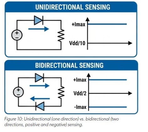
Design Tip : If the possibility for reverse current exists (such as during a fault event), use of a bidirectional sensor is recommended. In contrast to a bidirectional sensor, in a unidirectional sensor, if current flows in the opposite direction, the sensor saturates.

Practical Example: Selecting a Sensor
Consider a battery-powered tool with a brushless DC (BLDC) motor that has the following current profile:
- Nominal Running Current: 8 A
- Peak Startup Current: 60 A
For this profile, a sensor with a ±20 A range provides excellent resolution of the 8 A nominal current but completely saturates during motor startup, which makes it impossible to monitor the 60 A peak.
A sensor with a ±100 A range easily handles the startup peak, but its lower sensitivity compromises measurement accuracy at the 8 A nominal current.
A sensor with a ±65 A range, such as the ACS37032LLZATR- 065B3, is an ideal choice. It provides sufficient headroom to accurately measure the 60 A peak and offers good resolution and SNR for precise control at the 8 A nominal operating point.
Through careful analysis of the full current profile of the system and an understanding of the tradeoffs between saturation and resolution, the proper Allegro current sensor can be selected with a range that ensures both high performance and robust, reliable operation.
Conclusion
The selection of a current sensor is a foundational design decision that directly impacts system performance, reliability, and safety. As this document details, the process requires a thorough understanding of the complete current profile of the system, from its nominal operating current to its highest peak transient events.
Through careful consideration of the tradeoffs between sensing range, resolution, and saturation—and through selection of the appropriate sensing technology, whether that is the proven reliability of Hall-effect or the high-fidelity performance of TMR—an engineer can ensure a design is both robust and efficient. The practical example of the BLDC motor illustrates that a methodical approach that balances all operational conditions is the key, both in the selection of a sensor that is perfectly matched to the unique demands of the application and for assurance of optimal results and longterm reliability.
This document is part of a comprehensive series providing current sensor selection guidance. For additional content in this series, refer to Beyond the Datasheet: Mastering Current Sensing Selection.