Guidelines for Leadforming Using Back-Biased Hall-Effect Devices
By Bradley Smith, Allegro MicroSystems, LLC
Introduction
One of the common causes of damage to the Allegro™ Hall-effect devices that are magnetically back-biased is from the various leadforming operations performed to prepare the device for final assembly. This application note provides specific information and general ideas to consider when designing tools to accomplish the final preparation of the device. The application note Guidelines for Designing Subassemblies Using Hall-Effect Devices, AN277031, must be used in conjunction with this document.
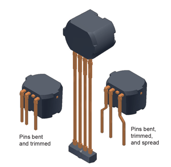
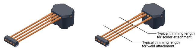
trimmed, and (right) leads trimmed and formed by spreading
The figures and notes in this application note are provided not as a comprehensive finished work on this subject, but only as illustrative of possible configurations to minimize harmful stress on the package, pins, and delicate internal wires. The ideas presented are based on experience with failure analysis in a production environment. As such, this document provides no guarantee or warranty from Allegro, and it is the responsibility of the user to fully characterize, qualify, and control their process.
Package Types
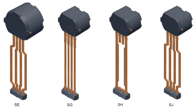
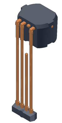
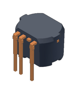
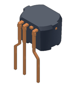
Figure 2 shows the general package configuration for the various package types of Hall-effect devices that Allegro offers with magnetic back-biasing. The SE package is similar to the others, and has spread pins, but has a larger package case and slightly longer pin length. There are subtle differences between the SE and the others that one needs to consider (see figure 3).
Packages SG, SH, and SJ share a common general package outline and pin length. They differ only in that the SH package has two trimmed pins (the remaining two pins also are somewhat wider than the SG and SJ) and the SJ has pins that are spread, while the SG and SH pins are straight.
The SE, SH, and SJ packages require no pin spreading by the user, and the pin configurations make it easier to weld the pins in comparison to the SG package. Therefore if a process is currently
using an SG and spreading the pins, the SJ should be considered as a replacement, if available for that device.
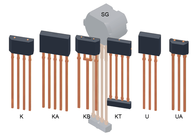
(Note: This application note is focused on packages with integrated back-biasing. Allegro also offers other long-pin packages without back-biasing, but with potentially similar leadforming requirements. These packages are shown in figure 4.)
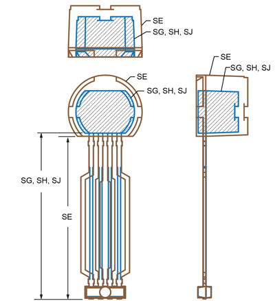
outlines (All four packages share a similar overall configuration, but the SE case
is rounded at the top, the SE case is larger, and the SE pins slightly shorter. The
SE and SJ have similar pin spreading, while the SG and SH have straight pins,
with the SH inner pins trimmed, as can be seen clearly in figure 2.)
for comparison of scale)
Leadforming Process Concepts
This section discusses some general considerations for designing a leadforming process.
Clamp Design
Clamps should be designed with the following features in mind:
- Quick and repeatable placement (choose low-abrasion device features and approach paths)
- Appropriate pressure (compression witness marks should be visible, but without excessive disruption of pin surface plating, while preventing movement of the pins at the case surface)
- Minimize downtime using quick disconnects (design fixtures so they can be swapped out, to allow off-line maintenance)
- Ease of maintenance and cleaning (design fixtures so they can be locked and unlocked by simple pin or clamp; eliminate recalibration by designing datum surfaces)
Clamp Placement
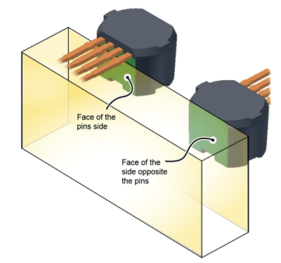
Allegro back-biased devices are designed with flat surfaces on the sides of the molded cases, as shown in figure 5. These flats can be used in combinations for optimal alignment during leadforming in automated processes, where high pressure must be applied to resist device movement during the process. The device can be placed for alignment against datum surfaces, as shown in figure 5, allowing them to be held steady while clamping pressure is then exerted solely on the pins. This prevents excessive force being exerted on the package interior.
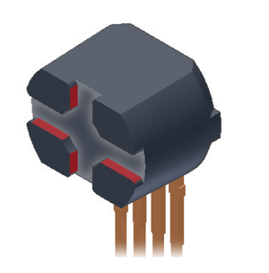
Additional coarse orientation recesses are provided at the rear of the cases, shown in figure 6. These are oriented orthogonally relative to the x and y axes of the Hall elements, and may be used
in the angular orientation of the devices during assembly into the final carrier.
The recesses should not be used for alignment during highvolume automated leadforming operations. The material of these features is relatively abrasive. Wedging an alignment tool into them with a fit tight enough to resist leadforming forces requires sliding against the abrasive material. This can quickly wear away tool edges, degrading alignment. Therefore, these features should not be used for fine alignment in leadforming. Using the flat sides of the device cases is recommended because the tool does not have to scrape against the case material.
Clamp Pressure
The goal of effective clamping is to securely isolate the pin roots, package case and internal electronic connections from any stress propagating from leadforming operations. Thus there should be sufficient clamping force to produce a “compression witness mark” in the plating on the upper and lower faces of the pins (this serves as a quality and process control check that the clamp force is adequate). However, the clamp should be carefully adjusted so that the force does not produce excessive crushing of the pin base material or excessive displacement of the pin plating.
As a general guideline, the witness mark should be optically apparent, creating a shiny band across the entire width of the pin. This shine results from the flattening effect of clamp compression on the matte tin plating. On close inspection, a typically good clamping pressure results in two parallel shiny bands from the edges of the clamp jaw, separated by a very slightly indented area from the face of the clamp that is less shiny than the parallel bands, but more shiny than the area that the clamps did not contact (see figure 7). This compression witness mark pattern should be:
- apparent on both sides of the pin
- embossment equally deep on both sides of the pin
- uniform across the entire width of the pin
- perpendicular to the sides of the pin
- uniform across all pins that were clamped simultaneously
Again, slight deformation of the plating on the pins is acceptable, but it should not threaten the structural integrity of the pin itself.
allow reliable orientation with minimal contact.
in the final assembly module or carrier, but they should not be used in
tight-tolerance automated operations for orientation because of tool wear
against the abrasive case material.
Clamp Maintainability
Two common causes of degraded clamp performance are:
- accumulation of debris
- wearing of bearing surfaces
Both are inevitable results of repetitive manufacturing processes, but should not be allowed to reduce productivity and quality. Maintenance of these items should be planned, using a schedule developed with a statistical preventive maintenance program, and cleaning and tool swapping should be facilitated by anticipatory clamp design.
- avoid scraping any surfaces
- allow removal of enclosed areas for rapid immersion cleaning
- allow quick release replacement of bearing surfaces
The first item requires work station design that allows tangential contact. The second and third items can be accommodated by designing moveable fittings. One method, illustrated in figure 8,
is to mount two fixtures on an off-the-shelf linear bearing. The two fixtures can be swapped by simply moving them on the bearing. Precision bearings are readily available with built-in locking
levers to hold the fixtures in place. The tools can be removed from the stages on the bearing, or serviced in place, while production continues with the tool on the other stage.
Work Station Design
Ideally, the fewest possible stations should be used:
- The most stringent tasks, the orientation of the device and pin clamping, can be performed the minimum times; if more than one clamping must be performed, placement should be replicated
- Each task requires the minimum duration (multiple stages operated in tandem require that all operations be performed at the speed of the slowest operation)
- Translation time (movement of devices from one station to the next) can be minimized
- Setup time (positioning tools for the next stage) can be minimized by prepositioning tools while previous stage is completing, and the next operation can commence while tools for previous
stage are clearing
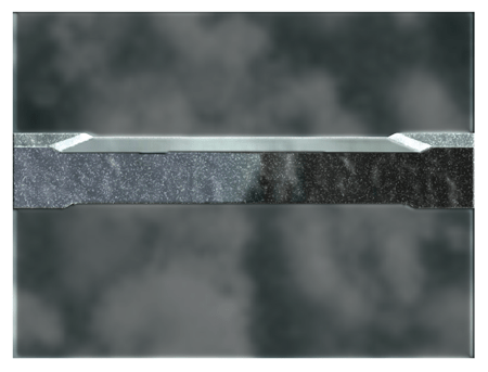
proper clamping. Dual shiny parallel bands should uniformly extend
across the pin on both sides.
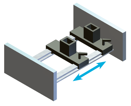
swapping tools in-line.
Pin Bending and Trimming
The processes illustrated in this section can be accomplished in as few as one clamping stage. This clamping is used to position the device for trimming pin 3, and then bending and trimming the remaining pins. In the next section, optional spreading of the remaining pins is described (for SG packages only, which have four full-length straight pins). A second clamping would be used in that case, because of the specialized tooling.
Note that many devices are available in the prebent SJ package, and this package should be selected when available, instead of performing bending after manufacture.
Stage 1. Orientation and Clamping
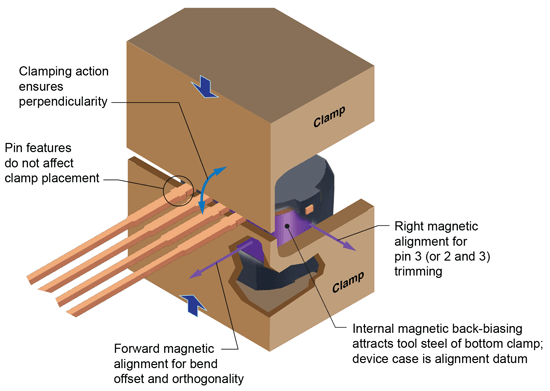
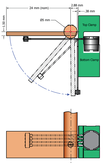
Figures 9 through 14 illustrate the critical considerations for the beginning step in the leadforming process, the initial clamping of the pins. This design uses an opposing top and bottom dual clamp (figure 9). It is assumed that, prior to this step, the user has set up a tape-and-reel splitter station to peel off the cover tape and engage a robot arm to magnetically pick up the device from the pocket, orient it correctly, and place it into the pin clamp tool.
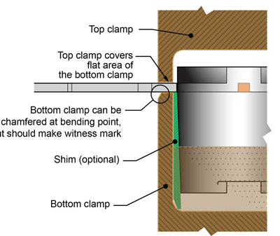
A simple clamp tool can be fabricated that takes advantage of the magnetic characteristics and the package case surfaces to mount the device with precision and repeatability. This pin clamp tool design illustrates the idea of using the package case flat under the pins, and the side of the package case, to orient correctly (in two dimensions) the package case against the bottom clamp inner face (figure 10). Figure 11 illustrates the primary features of the bottom clamp (see detailed view in figure 12). The perpendicularity of the operations is controlled by the clamping action itself, exerted by the top clamp, which can be a simple bar. The idea of this clamp setup design is to securely isolate the package case and pins from any stress propagating to and into the package case.
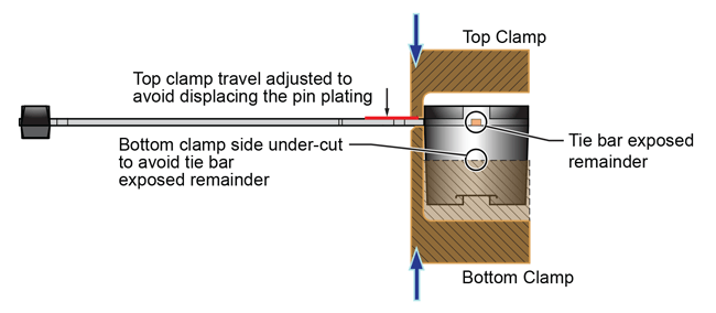
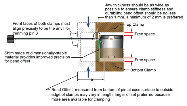
Note that the bottom clamp has a width under the pins that is set to the bend offset, the separation of the pins from the package case after a 90-degree pin bend (see enlarged view in figure 13). If greater distance from the package case is needed, a shim attached to the inner bottom clamp can be used.
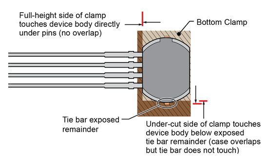
The package case is not in contact with any surface, top or bottom, except a front edge under the pins and one point on one side (see figure 10) which provide orientation to the clamp, while the device is conveniently held in position by the magnetism in the device. Thus the package case is essentially “free,” held in midair. The package case orientation is such that it is consistently held at the proper height and at 90 degrees to the bottom clamp solely by the clamping action of the clamps themselves.
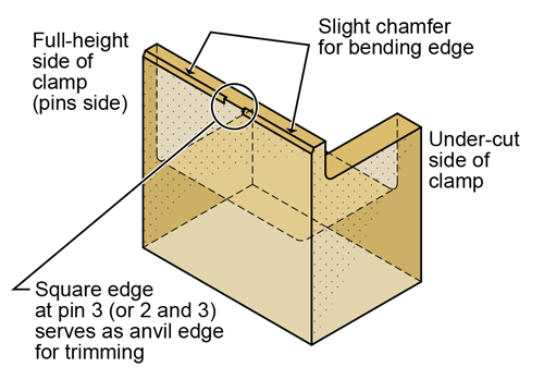
The detail drawing (figure 13) shows that the bottom clamp has a slight chamfered radius on the outside edge of the clamp to allow the inner bend area of the pin to form without undue stress. Note
that the portion of the front edge directly under pin 3 is not chamfered, but maintained at a sharp right angle to support a clean trim of the pin.
The only other consideration needed is the orientation side-toside on the clamp (this is important for the pin 3 removal step). This can be accomplished by a side wall on one side of the bottom clamp. There should be only one side wall, so that it can be attracted by the magnetism of the device, allowing the side of the device to act as the datum for left-right alignment of pin 3 for trimming.
the leadform operation forces from the case; as a good practice, ample free space should be left above
and below the device body, to avoid incidental pressure that could disturb the internal wiring connections
rather than bent, there should be no chamfer under those pins, and a sharp 90-degree edge
should be present instead (see figure 11)
in mounting and alignment in the clamp
Stage 2. Trimming Pin 3
Pin 3 is a test and diagnostic pin on many devices, and typically is not used in the final application, so is trimmed and/or connected to a ground pin in the customer assembly. With the SH package, which is often used for 2-wire devices, pins 2 and 3 are factory-trimmed but are often trimmed close to the package body by customers.
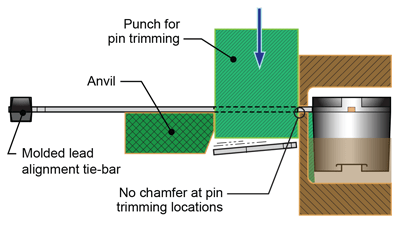
To trim the pins, the top and bottom clamps from the previous step can be used as an anvil on the package side of the pin (note that under pin 3 there should be no radius or chamfer and should instead be a sharp 90-degree edge).
The tie-bar side of the pin should be supported by an anvil that comes into place under the pin prior to the punch trimming the pin. The distance of the anvil edge from the package case should be set in relation to the final, 90-degree pin bend and the length of the untrimmed pins, such that there is no interference of the trimmed remainder with subsequent process steps, such as trimming pins 1, 2 and 4 (see figure 15).
that it is not necessary to remove the package from the clamps, if the clamps are
designed to also be used in the next step, bending by roller forming
Stage 3. Forming the 90° Pin Bend
Now the pins are ready to be formed. There are two common methods of pin bending: paddle forming (fixed bearing surface) and roller forming (rotating bearing surface). Although both methods have benefits and liabilities, Allegro recommends roller forming. When paddle forming is used, the pins should not be formed against the package body itself because of likely damage to pins and electrical connections inside the package body. Instead, Allegro only endorses paddle forming if the pins are properly clamped and forming takes place against the clamp face.
Paddle Forming
Paddle forming against the package body is not recommended because force can be transferred to the internal wire, potentially causing breakage. However, if top and bottom clamping is used on the leads, paddle forming can be used. Because of the stresses, the thickness of the clamps at the jaws should be thicker for paddle forming than is required for roller forming.
The paddle forming tool should be on a rotating shaft with the bearing face of the paddle aligned along the axis of rotation of the shaft. Ideally, the rotational profile is tangent both to the original plane of the pins and to the final plane of the pins after bending.
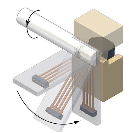
upper panel; in this example, the rod supporting the paddle blade has a
5 mm diameter where it passes by the package.
not provide for pin spring-back after forming
The bearing surface of the paddle should be extended the full length of the pins, over the tie-bar. This allows the maximum distribution of force during bending. The mount of rotation should be carefully set to stop with enough room left to accommodate both the thickness of the pins and the Bend Offset (the thickness of the clamp and any shim), to avoid crushing the pins against the clamp itself. By applying pressure on the tie-bar a slight overbending is possible if required.
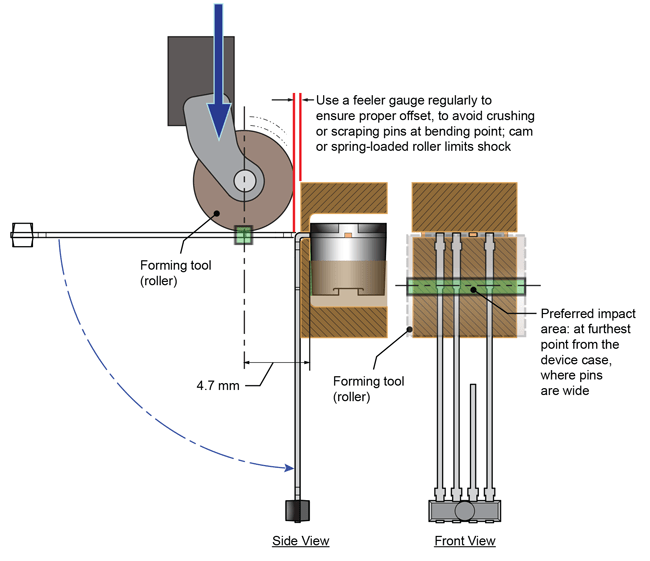
Roller Forming
A slide-by or guillotine forming tool uses extreme force against the pin, scraping and wiping the plating, and nearly shearing the pin if set too closely. Therefore it is not recommended. The recommended forming tool is a roller forming head, which rolls across the pin with minimal friction to make the 90-degree bend, while the device is firmly clamped (figure 19). Roller forming is the least damaging method of leadforming, and, when properly clamped, does not put any stress on the package case or internal wires.
The diameter of the roller should be optimized for impact on the pins. In general, the larger the diameter, the further away from the device case the impact occurs, and the less required clamping force. However, impact should occur where the pins are widest, which occurs relatively near the device case. The point of impact should not be where the pins are narrow.
Note that the roller position must be carefully set, monitored, and maintained such that the roller is not set closer to the clamp than the thickness of the device pins (so that the pins are not flattened, nor plating excessively damaged).
When bending metal, there always are a few degrees of springback. Usually, this is not critical, but if spring-back is not acceptable, when using roller-forming, a slight bevel can be made to the bottom clamp to allow slight over-forming of the pins below the clamping face (figure 20). The positioning of the roller can be made with cams to accommodate an over-forming in this area. The effect, however, is marginal.
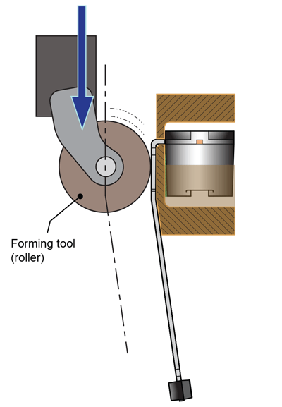
accommodate pin spring-back
Stage 4. Trimming Pins 1, 2, and 4
The remaining pins can now be trimmed to final length below the lower clamp, using the lower edge of the bottom clamp body as an anvil (figure 22).
Punch
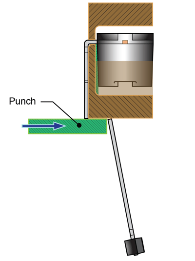
an anvil on the bottom edge
Stage 5. Extraction
The Allegro back-biased devices have an internal magnetic pellet that aids orientation of the device in the clamp during leadforming. When leadforming is complete, the magnetic attraction can be used to extract the device from the clamp. However, the attraction to the clamp must be overcome before a magnetic pick-up can be used to extract and transport the device to the next workstation.
As shown in figure 24, the first stage of the extraction procedure is to release the top clamp and remove it to provide access for the pick-up. The device remains held in the bottom clamp because the back-biasing magnetic pellet is located in the lower portion of the device, and so the device is less attracted to the top clamp than to the bottom clamp.
In the second stage, a mechanical shelf, which can be integrated into the bottom clamp, is used to lift the device away from the bottom clamp, where the magnetic attraction is strongest. Note that the device is also magnetically attracted to the sides and the front of the bottom clamp, so care must be taken to avoid lifting the shelf too high and allowing the device to jump out of the confines of the bottom clamp. As the device is lifted, it will shift slightly as the sloped sides move up the wall of the clamp.
In the third and final stage, a ferromagnetic pick-up can be used to overcome the remaining magnetic attraction to the clamp, and lift the device for transport to the next workstation.
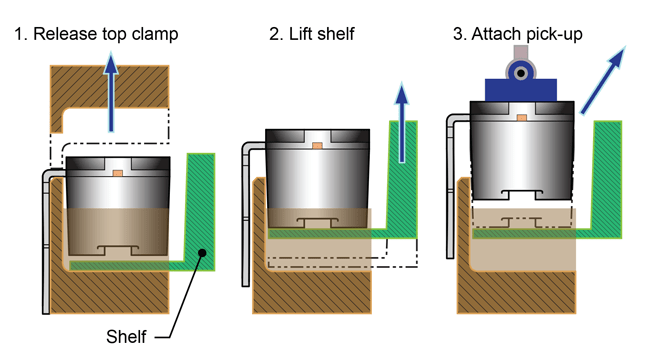
device from bottom clamp, allowing device extraction by a magnetic pick-up
Optional Pin Spreading
The SE, SH, and SJ package configurations have spread pins, which is convenient for providing sufficient clearance for weld head electrodes to make contact or for soldering. If these packages are not available for the required device, and an SG package (or one of the other packages with straight pins) is used, pin spreading may be required to provide clearance in the final carrier assembly.
Stage 1. Clamping
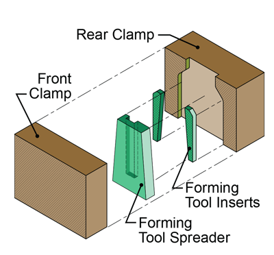
One possible solution is illustrated in figures 25 and 26. The fixture has three types of components:
- front and back clamps, used to constrain the device pins and guide the movement of the other tools
- forming tool inserts, used to press the pins into the recesses of the back clamp
- forming tool spreader, used to apply angular force uniformly against the insert tools
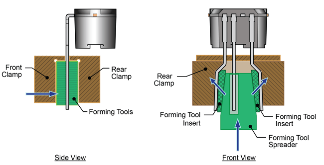
Stage 2. Pin Bending
Each of the two pins being spread are formed by application of force at one location (the radius bend of the corresponding tool insert) and then further pressed against the forming body of the rear clamp so that the result is a parallel spread of the pins. Both side pins should be spread, simultaneously, to balance the stresses in the process. Spring-back can be accommodated by a slight
bevel to the forming body.
Note: Allegro strongly advises against manual forming of pins. Use of a robotic arm to insert device pins into a forming jig provides the critical quality enhancements for better repeatability and statistical process control (SPC). The following points should be carefully monitored and optimized:
- Acceleration, velocity, and force of insertion
- Loading of tool surfaces and scraping of device pins
- Distance of insertion (do not overdrive beyond the proper set height dimension)
Conclusion
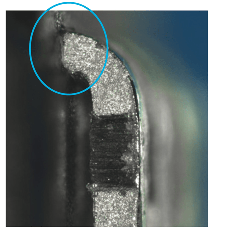
Figures 19 and 20 demonstrate the results of applying clamping procedures such as those described in this document (figure 28) and the contrasting result of not properly clamping (figure 29). However, a much greater concern is the internal damage that can result to wiring and wire bonds if the pin is not clamped to sufficiently isolate the internal device structures from the dynamic forces of leadforming.
This type of damage may not be immediately evident, but may later appear due to vibration or recurrent thermal expansion and contraction. Thus, it is most effective to avoid the risk of damage by a well-designed and maintained tooling strategy.
Allegro must emphasize that the information provided in this document is for initial reference only. The dimensions, materials, and techniques described must be considered and refined to fit the particular process requirements for each application.
For further information on the Allegro packages discussed, or advice regarding leadforming operations, contact your local Allegro field service representative.
Also on the Allegro website, in the Packaging section, the Plastic Biased document provides reference dimensions for the devices described in this note.
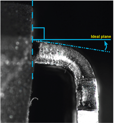
above and below the pin was used. Ideally, there should be no deflection
of the pin from the perpendicular, however, a slight amount may be
acceptable.
clamping was used and the pin too close to the package case. Circled
area of disturbance indicates potential internal damage.
Appendix A
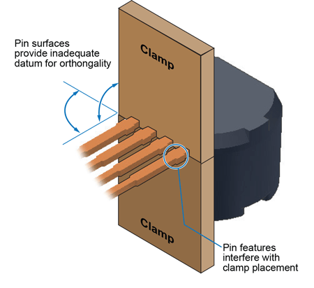
Comb Clamping
One of the tools that should not be used is the interdigitated comb clamp, illustrated in figure A-2. This clamping configuration results in slivers and splinters of the plating and of the pin base material because of slight misorientations of the pins. Also, because the dambar protrusions result in a greater width than the nominal pin width, special attention is required to avoid interference with them or crushing them. An example of the damage that can result appears in figure A-1.
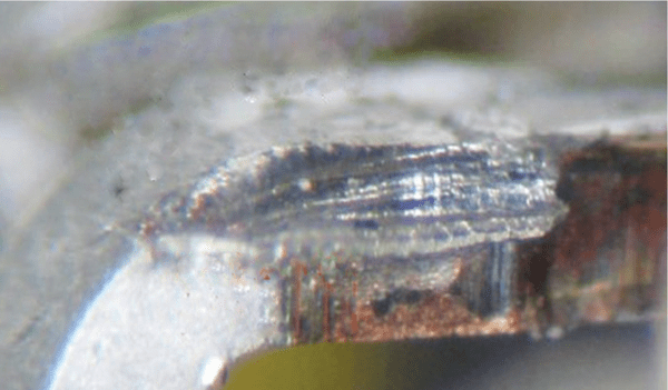
area being 0.1 mm wider on each side than the nominal pin width, and also because the pins were misoriented (rotated)
relative to the comb clamp.
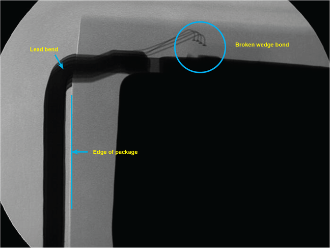
No clamping of the leads was used. The result was that the wire wedge bond was broken due to physical trauma upon
the lead due to the bend without clamping.
Preventive Maintenance
If misaligned leadforms or damaged device electronics appear in post-production inspections, the preventive maintenance program has already failed, requiring retesting and rejections of assemblies, as well as line downtime and repair. A successful preventive maintenance program is based on statistical projections of wear and debris, so that clamps can be swapped out for maintenance at a convenient time and before degradation of product.
Units should be inspected for:
- changes in deformation
- changes in the compression witness marks
- changes in the bend radii
Tools should be inspected for:
- wear
- build-up of residue
Results should be compiled in trend charts.
A feeler gauge should be used on a regular basis to ensure the critical separation dimensions in the paddle or roller forming tools. The center of rotation of the paddle or roller must be maintained so that the pins are not overly compressed against the bottom clamp.
Clamp Maintenance
Collisions between tools, such as the interdigitated comb clamp, and the device pins result in loading the tools with the plating material from the pins. This can relatively quickly result in loss of dimensional control. Tools should be routinely inspected for loading and critical dimensions measured.
Although copper core material and pin plating are soft relative to tool steel, the close tolerances for bending and trimming, and the tight bending radii, lend a relative stiffness to the pins that can erode tool steel with surprising rapidity. Tools should be routinely inspected for wear and critical dimensions measured.
Lubrication is not recommended for extending tool life. Experience has shown that lubricants attract shavings, dust, and other waste materials, resulting in the lubricant becoming a medium for
scoring and deforming pin surfaces.
Tool steel edge orthogonality and surface flatness can be preserved for an extended period of time by protecting wear areas with diamond-like material coatings (DLC), or carbide surfaces may be used (although with shorter life than DLC).
Control Plan, FMEA, and PM Schedules
A good process should have a well defined control plan with identified tolerances and specifications of dimensions, an appropriate FMEA (Failure Mode Effects Analysis) and a preventative maintenance schedule designed to keep the process tools in original condition and tolerance. Data should be collected and charted as a trend chart (using SPC-like parameters) with upper and lower specification limits, upper and lower control limits, target values, data distribution charts (with identification of whether the process is to be controlled as a normal or a skewed distribution).
The following detailed list of items pertaining to the leadforming process should be considered for the above schedules and controls:
- Magnetic pick-up of the device from the carrier tape. Check the steel pick-up for magnetic filings and debris, set the pickup height, set the put-down height, and check and measure
tolerances on height and positions. - Clamping. Set the top to bottom clamp height and pressure. Check witness marks on the leads. Clean the bottom clamp “L” so that orientation is consistent.
- Trim pin 3. Set height of the pin 3 anvil, pin 3 punch, and check the sharpness of both. Clean both surfaces.
- Forming tool. Set the height of the roller forming tool, set the distance from the package body, including leads, so that overbending is avoided. Do the same if using a paddle bend.
Set the rotation pivot point center to avoid overbending of both. Clean the rollers or paddle to remove plating residues. - Final Trim. Set the height of the trim tool, check the sharpness of the tool and anvil, and clean both.
- Lead Spreading. Set the height, movement distance travel, and drive distance. Clean all surfaces, and check for wear of surfaces and tolerances.
Copyright ©2011-2013, Allegro MicroSystems, LLC
The information contained in this document does not constitute any representation, warranty, assurance, guaranty, or inducement by Allegro to the user with respect to the subject matter of this document. The information being provided does not guarantee that a process based on this information will be reliable, or that Allegro has explored all of the possible failure modes. It is the user’s responsibility to do sufficient qualification testing of the final product to insure that it is reliable and meets all design requirements.