Relationship Between False-Alarm Rate and Probability of False Alarm
Introduction
The relationship between the probability of false alarm, as calculated from the false-alarm rate (FAR), and the probability of detection as it relates to measuring target distance with a lidar system, are discussed.
Far and Probability of False Alarm
In a time-of-flight (TOF) lidar system, the travel times of laser pulses between sensor and target are used to estimate the range to a target. In the TOF method of range estimation, a short laser pulse is transmitted and is subsequently reflected from a target. The times of laser pulse transmission and reception of the backscattered pulse are measured by one or more photoreceivers. The TOF is calculated as the time between the transmission and the reception of the pulse, and the range to the target (R) is calculated as a function of the average group velocity (c) of the laser pulse given atmospheric conditions along the path between sensor and target, on the basis of the relationship:
Equation 1:
R = TOF/2 × c.
In practice, application requirements play a major role in determining the maximum range of a lidar system. A lidar system can provide useful measurements to a maximum distance where the probability of detecting the target (Pd) remains greater than some value determined by the application requirements (generally specified to be between 50% and 99%). In the absence of a specific application, Pd is generally challenging to specify because Pd depends on many target properties—range, specular and diffuse reflectance, size, orientation, and topography—as well as the intervening atmospheric properties.
When configuring a lidar system, Pd is often specified relative to the probability of false alarm (Pfa). The Pfa is the probability that a false alarm will occur at least once per ranging event to a target at a fixed distance. In practice, for a fixed range, this is accomplished by raising the pulse-detection threshold to a level where the resultant Pfa is at or slightly below the required performance value. At that threshold, the optical-pulse-signal power required to exceed the voltage threshold can be measured for the specified Pd.
For real-world problems, however, Pfa is not very useful because it is only relevant for target measurements at one specific range. Targets are not always at the same distance, and the Pfa changes as a function of the duration of the time of flight to those targets at various ranges. Moreover, the Pfa depends on background solar conditions and the ambient temperature, so direct measurement of Pfa is a process that quickly becomes too unwieldy for practical application.
The benefit of using a false-alarm rate to specify the performance of a lidar system is that FAR is easily and readily measured.
To measure FAR, false alarms—resulting from electronic noise or solar background—are counted within a unit of time (i.e., false counts per second). The FAR is the average number of false alarms per second at a given pulse-detection threshold.
False alarms are uniformly distributed in time and obey Poisson statistics. The expectation value of the number of false alarms as a function of range is calculated as:
Equation 2:
⟨FA⟩ = FAR × ( 2R ) / c.
When ⟨FA⟩ is much smaller than one, the expectation value of the false alarm count is also the probability of false alarm, Pfa. When ⟨FA⟩ is larger, as would be the case for low detection thresholds and long-range targets, Poisson statistics give the probability of at least one false alarm occurring as:
Equation 3:
Pfa = 1 – exp [ – ⟨FA⟩ ].
The maximum permissible FAR can be specified for any maximum permissible Pfa requirement using:
Equation 4:
FAR = –ln (1 – Pfa) × c / ( 2 R ) ≈ Pfa × c / ( 2 R ),
where the approximation is valid if ⟨FA⟩ is small.
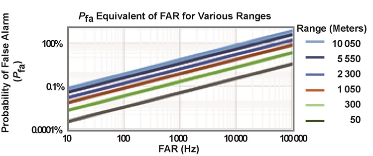
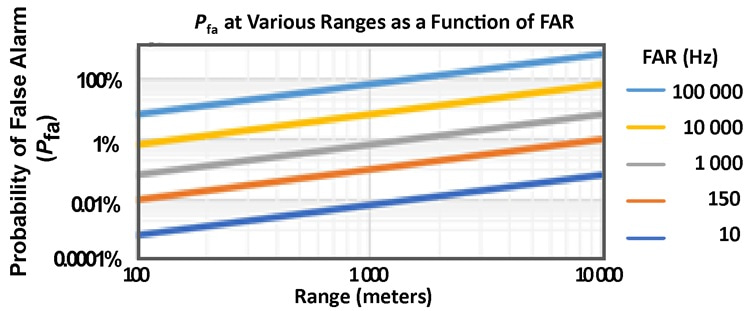
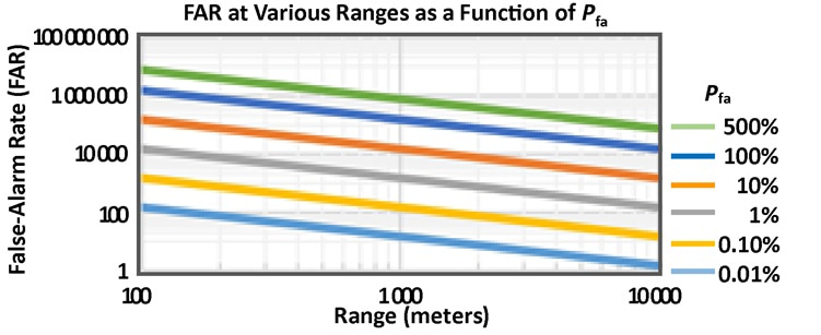
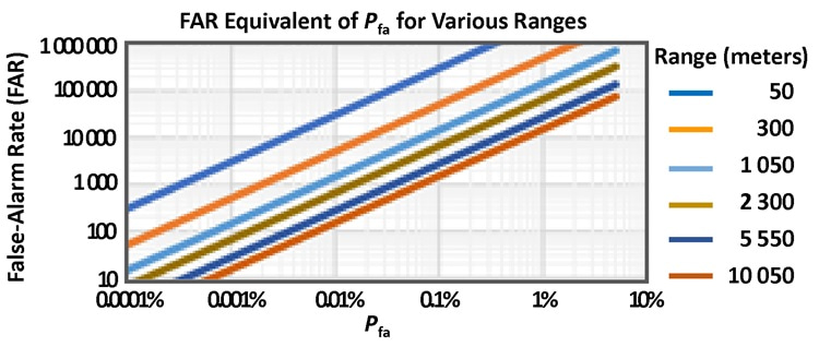
Pfa equivalents are plotted as a function of target range for various FARs in Figure 1 and as a function of FAR for various target ranges in Figure 2. Similarly, FAR values are plotted as a function of target range for various Pfa values in Figure 3, and as a function of Pfa for various target ranges in Figure 4.
Conclusion
The plots presented here show that achieving:
- 1% Pfa requires a FAR threshold of:
- 1,000 Hz for targets at 1,500 meters; and
- 250 Hz for targets at 5,000 meters.
- 0.1% Pfa requires a FAR threshold of:
- 100 Hz for targets at 1,500 meters; and
- 3 Hz for targets at 5,000 meters

Figure 1: Pfa equivalents for various FAR values at various ranges.

Figure 2: Pfa equivalents for various ranges for various FAR levels.

Figure 3: FAR values for various Pfa values, specified at various ranges.

Figure 4: FAR equivalents for various Pfa values for various ranges.