How Hardware Selection Impacts Driver Experience in EPS Systems
Introduction
Continuous innovation in the automotive market is inevitable. Automakers are tasked with maximizing the performance and efficiency of their end systems. For that reason, electric power steering (EPS) systems have become popular in automotive manufacturing, displacing their mechanical counterparts because they save space, weight, emissions, and reduce fit complexity.
While the electrical architectures of EPS systems are similar, there are areas where designers can differentiate their designs. By selecting the right hardware and taking advantage of their enhanced features, automakers can maximize the driver experience in a compact and functionally safe design.
EPS System Overview
The electrical architecture for conventional EPS designs can be broken down into the following subsystems, seen in Figure 1:
- Digital processing
- Communication
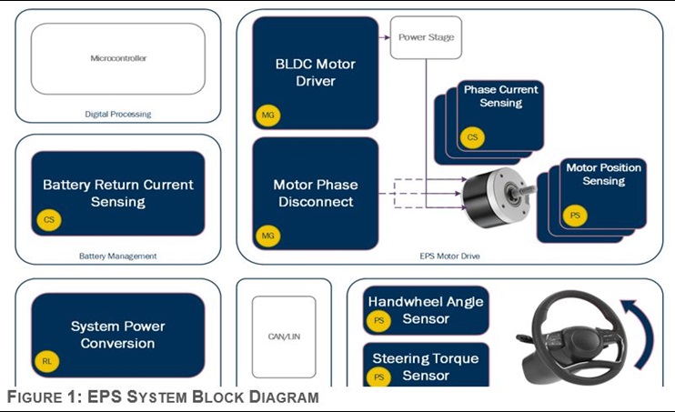
Within each subsystem, there are trade-offs to be made which can impact the performance and efficiency of the system. At its most basic functionality, the steering wheel interface uses a handwheel angle sensor and steering torque sensor to register input force and direction; the EPS motor drive uses a highly integrated gate driver to drive a torque assist motor fixed to the column or rack to provide the steering force. How these devices are selected can impact the driver experience.
Maximizing Driver Experience
Significant effort has been put forth in minimizing unwanted byproducts inherent in a motor-assisted electric power steering system, such as reducing torque ripple and improving system response. While usually driven using a sophisticated control algorithm, they still rely on a control network to feedback high-quality data and a responsive gate driver. Selecting the right hardware can be the difference in creating a consistent smooth steering experience.
Torque Ripple
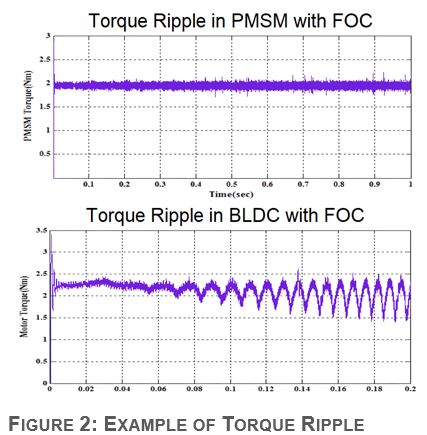
Reducing the torque ripple inherent to BLDC control is the highest priority. Torque ripple is the phenomenon where the force applied by the motor to the load oscillates and can lead to a feeling of counter steering or vibration in the wheel. If employing a PMSM with FOC control, the designer can achieve very minimal torque ripple in the end system, illustrated in Figure 2 (K and Giridharan 2015).
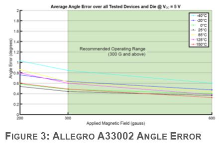
Torque ripple can be greatly improved by the level of detail the controller has about the positioning of the motor. The ability to detect within a degree of accuracy is necessary to prevent large oscillations in the assist motor that will be felt on the column. Low-noise, low-error 2D angular sensors from Allegro can be implemented for providing motor positioning and handwheel feedback, supporting as low angle error and angle noise, seen in Figure 3.
Another way to reduce torque ripple in the system is by improving the accuracy and error in the current sensing mechanism. Torque applied by a motor is directly proportional to the current through the windings. The two methods most typically used to measure current are low-side sensing or in-phase sensing, each with their own benefits and limitations, as shown in Figure 4.
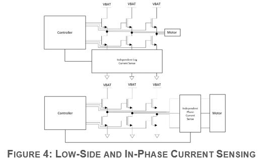
In-phase current sensing provides accurate data of the currents flowing in each phase which reduces software complexity. Due to the nature of the design, current sensors will need to support ≥100 A maximum current with low noise and high accuracy. Allegro Hall-effect current sensors can provide accurate measurements, unaffected by common-mode transients on the phase nodes that standard shunt current sense amplifiers (CSA) may struggle with.
Low-side sensing is an alternative method to measure current but can only sense while the low-side FET is on and will require additional firmware development to recreate a complete phase current. Using CSAs that are integrated into Allegro motor drivers can enable designers to save space and reduce the cost comparative to discrete in-phase sensing.
System Response
Another component of user experience is the ability to respond instantaneously to driver input. To achieve similar response in an EPS system, the feedback loop for driver input requires low-latency and can benefit from a higher motor drive frequency.
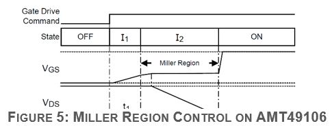
All PWM switching topologies are susceptible to rise and fall time  transients, which can cause system faults and force designers to lengthen blanking times. To reduce switching transients on phase nodes, designers should select a gate driver that supports Miller Region current control to dictate the VDS slew rate on the switching FET and prevent overshoot and shoot-through events, seen in Figure 5. Motor controllers offered by Allegro are designed to give designers control over these and other output stage characteristics.
When sensing in-phase currents the bandwidth needs to be sufficiently high, 5 to 10 times the PWM frequency as a rule of thumb, for sufficient sampling within the averaging window. Gate drivers selected for EPS systems typically switch near or above 20 kHz, striving to get above the audible range of humans. Allegro Hall-effect current sensors use a differential sensing mechanism to minimize common mode noise and enable designers to sense in-phase comfortably with motor driver PWM switching frequencies near 20 kHz.
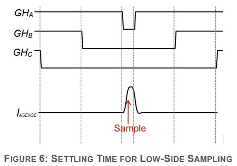
In the case of low-side sensing, devices may need higher bandwidth to reliably sense the current during the tON of the low-side FET. When the low-side FET has a short “on cycle”, the current has a settling time of about 1 µs which means a bandwidth upwards of 20 to 40 times the PWM frequency to guarantee the current is sampled accurately, as shown in Figure 6.
The accuracy of this data is critical for closing the field-oriented control current loop. Current sense amplifiers that are integrated into Allegro motor drivers support high bandwidth to enable designers to switch at higher frequencies and offer programable gain and offset for calibration.
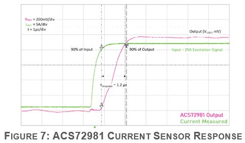
System response can also be hindered by slow sensor feedback. Allegro Hall-effect current sensors boast an incredibly low response, shown in Figure 7. Handwheel, motor position, and torque sensors offered by Allegro also grant quick response and necessary to support complex algorithms.
Through effective management of torque ripple and system response, designers can continue to improve the drivers steering experience. Selecting the optimal hardware can improve the quality of data, reduce the computational overhead required for BLDC control, and enhance the systems overall control over the assist motor.
Conclusion
Implementing an EPS system with exceptional driver experience is a considerably difficult task, but necessary for EPS manufacturers to differentiate themselves. Manufacturers can realize the full potential of their EPS system by using the right components to maximize driver experience and achieve functional safety standards with flexible implementation.
Allegro Recommended Solutions:
|
Subsystem |
Socket |
Part Number |
|
EPS Motor Drive |
BLDC Motor Driver |
|
|
Phase Current Sensing |
||
|
Motor Position Sensing |
||
|
Motor Phase Disconnect |
||
|
Handwheel Interface |
Handwheel Angle Sensor |
|
|
Steering Torque Sensor |
||
|
DC/DC Conversion |
System Power Conversion |
|
|
Battery Management |
Battery Return Current Sensing |
Based on the article, "How Hardware Selection Impacts Driver Experience in EPS Systems" by Zach Nelson, originally published in Autonomous Vehicle International, January 1st, 2023. Republished with permission. For portions not copyrighted by original publisher, Copyright ©2023, Allegro MicroSystems, Inc.
Copyright 2023, Allegro Microsystems.
The information contained in this document does not constitute any representation, warranty, assurance, guaranty, or inducement by Allegro to the customer with respect to the subject matter of this document. The information being provided does not guarantee that a process based on this information will be reliable, or that Allegro has explored all of the possible failure modes. It is the customer's responsibility to do sufficient qualification testing of the final product to ensure that it is reliable and meets all design requirements.
Copies of this document are considered uncontrolled documents.