Ring Magnet Speed Sensing for Electronic Power Steering
Proper control of Electric Power Steering (EPS) systems requires both speed and direction information from the steering input shaft. This control will typically come from both high-resolution speed information and fairly coarse position information.
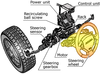
Figure 1. Typical EPS System
A dual multi-pole ring magnet can be used with a matrix of Hall effect dual output switches and latches to provide all of the required information. Figure 2 shows the configuration of the magnet with a high-resolution outer ring of alternating north and south poles and a low-resolution inner ring of alternating poles.
In order to determine the direction of the rotating magnet, a single Hall-effect sensor IC is utilized, with dual outputs from two separate bipolar Hall elements (A and B). ( Refer to figure 3. ) Because the two Hall elements are situated a distance apart on the surface of the IC, there is a phase lag in the signals generated by the rotating magnet.
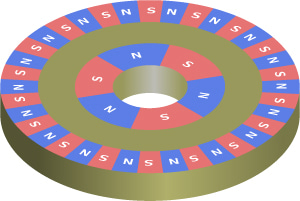
Figure 2. Dual Resolution Ring Magnet
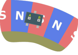
Figure 3. Ring Magnet with Dual Output, Bipolar Hall-Effect Device
With proper magnet pole spacing, the resulting output signals (Element A and Element B in figure 4) are in quadrature and are processed to provide two-state direction information. The element-to-element spacing for the device used in this example (a dual-output bipolar switch) is 1.5 mm. The optimum magnet pole spacing provides a peak signal in Element A and zero signal in Element B. This spacing corresponds to a dimension that is approximately equal to 3.0 mm between the alternating poles, or a pole period of 6 mm.
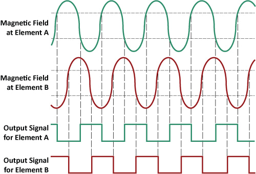
Figure 4. Quadrature Output of A1230
In order to obtain absolute position information, a state machine must be generated from the outputs of separate Hall-effect latching sensor ICs. The same phase delay that is induced in the pair of signals of the dual element device can be induced by devices in separate packages through proper package placement. If two device packages are placed at relative angular position that corresponds with the period of the magnet poles, then the output of the two ICs will be exactly in phase. However, if the package spacing is 1.25×(T/2), where T is the magnet pole period, then the outputs will be in quadrature. This will hold true for any multiple of this period, such as 2.25×(T/2), 3.25×(T/2), or 4.25×(T/2).
To generate a matrix of device outputs that provide a cascading phase delay, each device must be placed at an increasing fractional multiple of the magnet pole period. For instance, to get three devices with cascading outputs, device #1 can be placed in any location, device #2 can be placed 1.33×(T/2) from device #1 and device #3 can be placed 1.67×(T/2) from device #1.
Depending on the package size and magnet size, however, it may not be possible to the place the device packages very close together. This restriction is not a problem if the magnet poles are fairly consistent. With a repeatable magnetic profile, the fractional portion of the multiplication factor is the only pertinent value for establishing package placement. Using the previous example of three sensor ICs, the desired cascading output can be realized with a position of 1.33×(T/2) for device #2 and 2.67×(T/2) for device #3. See figure 5.
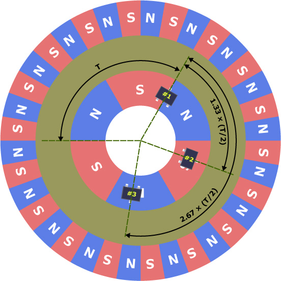
Figure 5. Matrix of Three A1220 Devices
With a coarse magnetic profile of three alternating north and south pole pairs, the use of three separate Hall-effect latches provides six discreet state combinations (A through F) that are repeated three times per magnet revolution. If a controller can track which of the 120° regions that a given package lies in, then the system position resolution is 20°. A benefit of this matrix is the ability to detect two fault conditions (LLL and HHH) that logically never occur. See figure 6 and table 1.
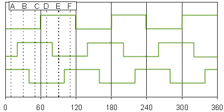
Figure 6. State Diagram for Three Latch Devices
| Table 1. State Diagram for Three Latch Devices | ||||
|---|---|---|---|---|
| Angular Position (°) |
Device #1 | Device #2 | Device #3 | Zone |
| 0 - 20 | L | H | H | A |
| 20 - 40 | L | H | H | B |
| 40 - 60 | L | H | L | C |
| 60 - 80 | H | H | L | D |
| 80 - 100 | H | L | L | E |
| 100 - 120 | H | L | H | F |
| 120 - 140 | L | L | H | A |
| 140 - 160 | L | H | H | B |
| 160 - 180 | L | H | L | C |
| 180 - 200 | H | H | L | D |
| 200 - 220 | H | L | L | E |
| 220 - 240 | H | L | H | F |
| 240 - 260 | L | L | H | A |
| 260 - 280 | L | H | H | B |
| 280 - 300 | L | H | L | C |
| 300 - 320 | H | H | L | D |
| 320 - 340 | H | L | L | E |
| 340 - 360 | H | L | H | F |
| DNE | L | L | L | |
| DNE | H | H | H | |
Alternative Solution
Allegro™ also offers a complementary device to the dual output bipolar switch. The A3423 internally processes the output signals from two Hall elements and provides two separate signals that represent speed and direction, respectively. The use of the A3423 makes it unnecessary to have external processing circuitry that would otherwise be required to establish a digital direction value.
Suggested Allegro Devices
| Table 2. Suggested Allegro Devices | ||||
|---|---|---|---|---|
| Allegro Part Number | Temperature Ranges |
Package Types | Tape and Reel Available |
Comments |
| A1212 | E, L | LT, UA | Yes | Sensitive latch |
| A1214 | E, L | LH, UA | Yes | Sensitive latch |
| A1220 | E, L | LH, UA | Yes | Very sensitive latch |
| A1221 | E, L | LH, UA | Yes | Sensitive latch |
| A1230 | E, L | K, L | Yes | Dual output bipolar switch |
Typical Applications
- Automotive EPS or EPAS
- Industrial machinery
- Recreational power steering