Guidelines for Using Allegro Angular Sensors
Introduction
Many applications in different industries, such as in industrial automation and automotive sensors and actuators, require monitoring the angle of a rotating shaft either in an on-axis or off-axis arrangement. This application note is dedicated to a review of on-axis magnetic applications.
Magnetic sensor integrated circuits (ICs) are commonly used to perform this task. This document provides guidelines for using angle sensors based on the Circular Vertical Hall (CVH) technology, which is the core of each Allegro angular position sensor mentioned within this article.
The design of any angle measurement system is based on the needs of the particular application, such as air gap, accuracy, and temperature range, as well as the properties of the sensor. This document provides an introduction to magnet selection and an understanding of the influences that determine the accuracy of such systems.
A magnetic angle measurement system has two main sources of error:
- sensor IC related errors
- magnetic input related errors
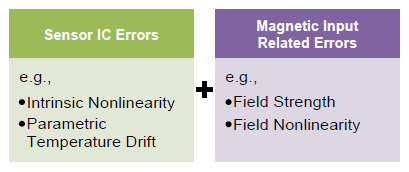
Figure 1: Angle Measurement Errors and Their Origins
Each Allegro sensor is tested and calibrated during production using a homogenous magnetic field. Intrinsic IC nonlinearity and temperature drift are therefore reduced to a minimum before the sensor is shipped to customers. Refer to product data sheets for temperature drift information.
When using a magnet in a design, the magnetic input will most likely not be homogenous, and the intensity of the field may not be constant over the rotational range. These are errors related to the magnetic input that cause measurement error in the system.
Field nonlinearity and field strength can contribute to the overall error of the system. Both depend on the mechanical position of the magnet relative to the sensing elements. In later sections of this document, nonlinearity will be described as accuracy error (refer to Accuracy Error Definition below).
Definition of Mechanical Dimensions, X/Y Sensing
In a Cartesian coordinate system, the sensor is considered a reference, with its package surface parallel to the X/Y plane. The center of the CVH transducer area is defined as the origin (0,0,0). The magnet will rotate around the Z-axis.
Ideally, the magnet rotation axis will be perpendicular to the X/Y plane, and there will be no offset from the origin (0,0). In the following section, offset from the origin will be referred to as “misalignment”, in other words, misalignment in Figure 2 is zero.
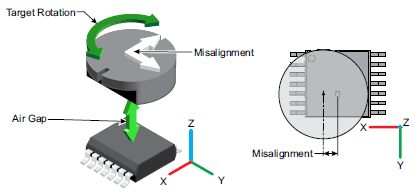
Figure 2: Application Placement
The distance between the magnet and the sensor along the Z-axis is commonly known as air gap. Refer to Figure 6: Air Gap Definition for details.
Sensing Element Location
The magnetic field is not uniform over the entire face of a typical magnet. The location of the magnetically sensitive CVH transducer needs to be considered in the mechanical design of the application. The sensitive area of the CVH transducer is defined in the datasheet for every Allegro angle sensor IC.
The dual die device shown in Figure 4 contains two identical chips in a side by side arrangement. This allows redundancy with very compact package outlines.
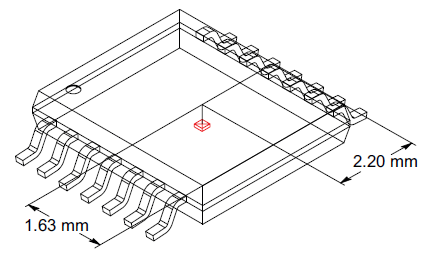
Figure 3: CVH Transducer Placement in the TSSOP-14 Package
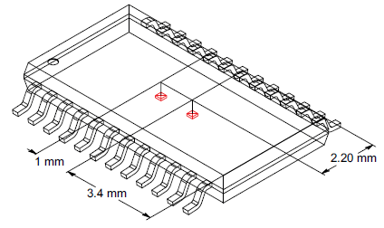
Figure 4: CVH Transducer Placement i the TSSOP-24 Dual Die Package
Magnetic Selection
The choice of magnets is not limited simply to type of material and size; there are also some basic shapes that serve as a good starting point for any system design. Three magnets have been chosen as examples for the measurements in later sections of this document.
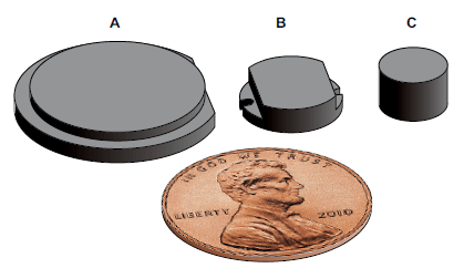
Figure 5: Size Comparison of the Three Magnets Selected
These magnet examples were selected to give basic guidelines. Magnets1 A and B in Figure 5 are designed specifically for angular sensors, and are available from the company Magnetfabrik Bonn GmbH in Germany.
Magnet C is a simple, diametrically magnetized disc with compact dimensions. Table 1 lists some of the characteristics of the magnets. For specific questions on magnet materials and shapes, please contact a preferred magnet material supplier.
| Magnet | A | B | C |
|---|---|---|---|
| Diameter | 18 mm | 9 mm | 6 mm |
| Height | 2.5 mm | 2.5 mm | 4 mm |
| Material | Sprox 13/21 p | Neofer 48/60 | Neofer 25/60 |
| Composition | Hard Ferrite + PA6 | NdFeB + PA11 | NdFeB + PA11 |
| Maximum Continuous Operating Temperature2 | 160ºC | 140ºC | 140ºC |
| Temperature Coefficient of Remanence | -0.19%/K | -0.12%/K | -0.12%/K |
| Manufacturing Process | Injection Molding | Injection Molding | Injection Molding |
Parameter Definition
Air Gap
Two different air gap definitions can be used when talking about magnetic field sensors: package air gap and crystal air gap.
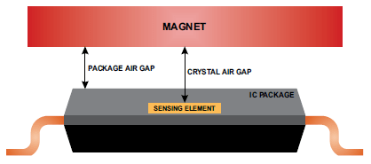
Figure 6: Air Gap Definition
Package Air Gap
Package air gap is defined as the distance between the top of the sensor housing and the nearest face of the magnet.
Crystal Air Gap
Crystal air gap is defined as distance between the sensing element in the sensor housing and the nearest face of the magnet.
In this document, air gap is defined as the crystal air gap. The sensing elements are 0.36 mm below the top surface of the package. Refer to Figure 6.
Angle Error Definition
Angle error is the difference between the actual position of the magnet and the position of the magnet as measured by the sensor device. This measurement is done by reading the sensor output and comparing it with a high resolution encoder (refer to Figure 7).
E = αSensor - αReal
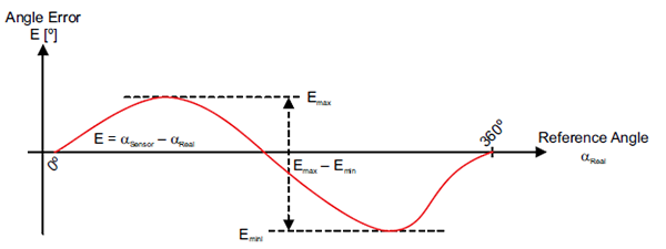
Figure 7: Angle Error and Accuracy Error Definition
Accuracy Error Definition
Further down in this document, the angle error is displayed as a function of misalignment. For that purpose, it is necessary to introduce a single angle error definition for a full rotation (refer to Figure 7). The ‘summarized’ angle error on one full rotation is defined as angular accuracy error, and it is calculated according to the following formula:
Angular Accuracy Error = (Emax – Emin) / 2
In other words, it is the amplitude of the deviation from a perfect straight line between 0 and 360 degrees.
Average Magnetic Field and Air Gap Dependency
The first step in the system design is to choose an appropriate magnet for the application air gap. Usually the air gap is in a range from 2 to 4 mm. Figure 8 shows the magnetic field as a function of air gap for the magnets shown in Figure 5.
By default, many Allegro angle sensors are trimmed to provide optimum performance at 300 Gauss (30 mT). However, unlike other angle sensors, Allegro sensors can be specifically trimmed for field strengths beyond 700 Gauss (70 mT). Please contact an Allegro representative for additional information regarding specific field strength trimming.
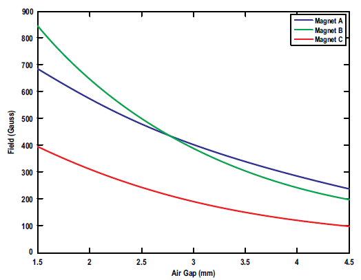
Figure 8: Magnet Field Regarding the Air Gap of the Three Magnets
Figures 9 through 11 show the angular accuracy error of Allegro’s A1334 IC when tested with the reference magnets. At each air gap, the magnet was rotated one full turn, and the angular accuracy error was calculated.
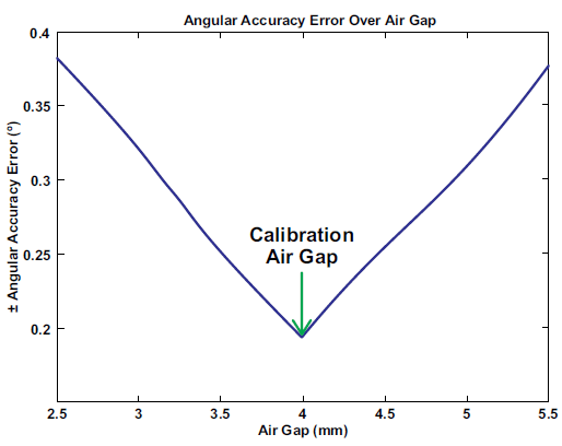
Figure 9: Magnet A, Angular Accuracy Error vs. Air Gap
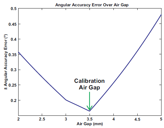
Figure 10: Magnet B, Angular Accuracy Error vs. Air Gap
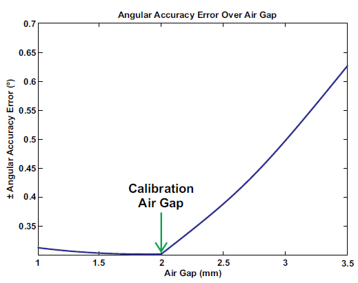
Figure 11: Magnet C, Angular Accuracy Error vs. Air Gap
Optimum air gaps are summarized in Table 2.
| Magnet A | Magnet B | Magnet C | |
|---|---|---|---|
| Air Gap | 4 mm | 3.5 mm | 2 mm |
In all three cases (magnet A, B, C), the angular accuracy error is influenced by the air gap. The best results are achieved at calibration air gap, that is, the distance where the magnet field strength equals the calibration field strength (300 G). Note that scales in Figures 9 to 11 differ.
Tolerance to Misalignment
As a result of mechanical placement tolerances, the CVH transducer will not always be placed perfectly in the center of the magnet. To understand how this misalignment can impact the accuracy of the measured angle, each magnet was tested with a different misalignment relative to its diameter.
The plots show the results of a multitude of measurements. The air gap was set to the calibration air gap (refer to Figures 9 through 11). Depending on its size, the magnet was misaligned by up to ±1.5 mm from the X/Y origin. At every point in the X/Y plane, the angular accuracy error was calculated for a full turn and displayed in colors. When comparing the plots, Figures 12 through 14, note that the scale differs.
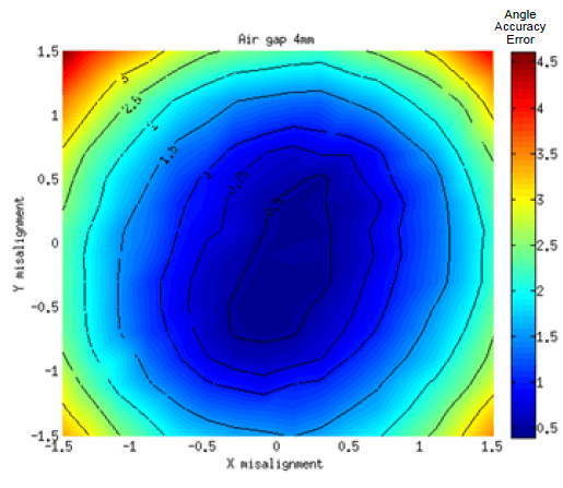
Figure 12: Angular Accuracy Error of Magnet A at 4 mm Air Gap
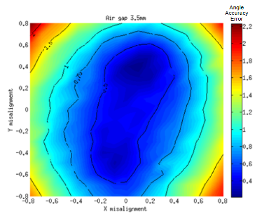
Figure 13: Angular Accuracy Error of Magnet B at 3.5 mm Air Gap
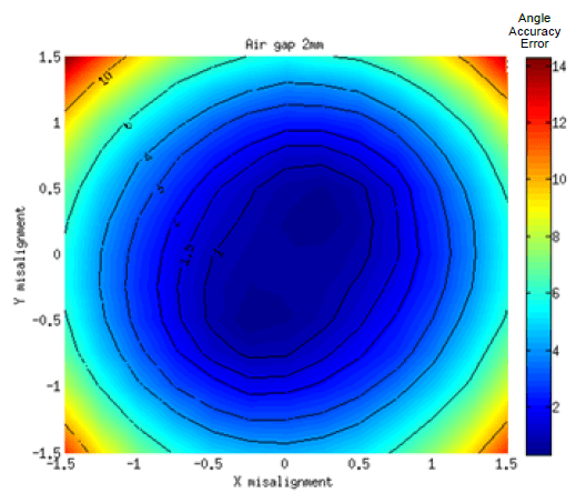
Figure 14: Angular Accuracy Error of Magnet C at 2 mm Air Gap
Summary of Measured Error
The plots provide answers to the following questions:
- What accuracy can be expected with a certain magnet and given mechanical placement tolerance?
- What magnet should be used for given accuracy and mechanical tolerance?
- What mechanical tolerance is allowable for a given magnet and accuracy?
| Angle Accuracy | Magnet A | Magnet B | Magnet C |
|---|---|---|---|
| 0.5º | ±0.5 mm | ±0.25 mm | ±0.1 mm |
| 1º | ±0.75 mm | ±0.65 mm | ±0.5 mm |
To demonstrate the tolerance to misalignment at different air gaps, magnet B was mapped with a misalignment of ±1 mm on X and Y axis at 2 different air gaps. Figures 15 and 16 demonstrate that tolerance to misalignment changes only slightly with air gap.
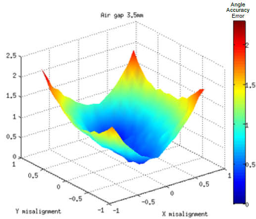
Figure 15: Angular Accuracy Error of Magnet B at 3.5 mm Air Gap
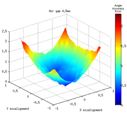
Figure 16: Angular Accuracy Error of Magnet B at 4.5 mm Air Gap
Repeatability
The repeatability of the angle reading depends on the intensity of the magnetic field input. A high input field improves signal to noise ratio. Applying this to magnetic sensors means that the repeatability is best at close air gaps. Figure 17 shows the standard deviation of 100 angle readings for different magnets. Depending on the possibilities of averaging in the application, this error may be negligible.
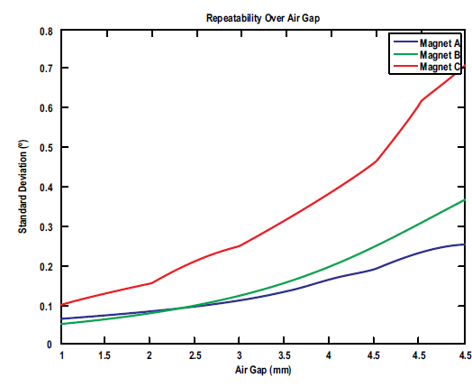
Figure 17: Standard Deviation of Angle Readings on Magnets A, B, and C vs. Air Gap4
Conclusion
Especially in harsh automotive or industrial environments, magnetic angle sensors have proven to be a valuable solution for sensor and actuator applications. Additional features, such as linearization, diagnosis functionality and redundancy, also support high safety critical applications, such as automotive steering systems.
The design of a magnetic circuit for angle sensors is a complex task, where many influencing parameters need to be considered. This document shows some of the interdependencies that exist between magnet selection, mechanical tolerances, and accuracy requirements for on-axis applications.
Please contact an Allegro representative for any remaining questions or support.
1 Magnetfabrik Bonn product reference numbers: 67.043-2 and 67.043-1.
2 Maximum operating temperature is determined by magnet material and shape. Exceeding these ratings can be tolerated for limited duration. Contact the supplier to select appropriate magnets for the application temperature profile.
3 Please contact Allegro for available options for specific input field range other than 300 Gauss.
4 Measurement done 100 time for each Air Gap (device in default mode 1 sample per reading).
Originally published in Design News, January 2015.