Improved Speed and Direction Sensing Using Vertical Hall Technology
By Marvin Ng, Allegro MicroSystems, LLC
Introduction
The A1262 2D dual-channel Hall-effect sensor IC is offered in a 5-pin SOT23W surface-mount package, as well as a 4-pin SIP through-hole package. It features operation with traditional planar—as well as vertical—magnetic field direction. The dual operation of the centrally located planar and vertical Hall elements results in:
directions (only X-Z or Y-Z axes, depending on
part number selected)
- Inherent 90° phase separation between outputs (quadrature), making quadrature magnet pole-pitch and air gap independent
- Smaller package size, allowing smaller PCB size and tighter Total Effective Air Gap (TEAG)
- X-Z option offers even smaller size-sensing TEAG
- Flexibility of mechanical design with the freedom to choose ring magnets based on availability and/or cost
- A potential replacement of through-hole devices, as in-plane sensing can be achieved with an SMT device
The two available options allow system design flexibility by sensing in the Y and Z axes or the X and Z axes. This allows the sensor IC, and therefore the PCB on which it is mounted, the flexibility to be mounted in different orientations, relative to the magnet.
The A1262 is an alternate solution for previous generation devices, such as the A1230 and A3425, whose 1D (dual planar Hall) design requires ring magnet pole spacing optimization and offers only one sensing orientation, while the A1262 does not require ring magnet optimization and can be configured in four different orientations (see Sensing Configurations section). Additionally the A1262 is offered in a smaller (SOT23W) package. See Table 1 for a comparison of the 2D A1262 to the dual-planar A1230 and A3425.
Table 1: Comparison of 2D versus 1D (Dual Planar)
| Characteristic | Device | ||
| A1262 | A1230 | A3425 | |
| Hall Element Spacing |
n/a |
1.0 mm |
1.0 mm |
| Inherent Output Quadrature |
Yes |
No | No |
| Sensing Configurations |
4 |
1 | 1 |
| Available Packages |
LH (SOT23W), K (SIP) |
L (SOIC), K (SIP) |
L (SOIC), K (SIP) |
| BOP / BRP (maximum) |
±40 G |
±30 G |
±30 G |
| Output Polarity, B > BOP |
Low |
Low | Low |
Vertical and Planar Hall Elements
Advances in IC design and fabrication allow the creation of vertical Hall elements sensitive to magnetic fields parallel to the plane of the IC. They function under the same principles of planar Hall elements, which are sensitive only to magnetic fields perpendicular to the plane of the IC. This Z-axis sensitivity is not altered by the
sensor IC orientation or rotation. As such, in-plane sensing is not possible using a surface-mount device with only a planar Hall element.
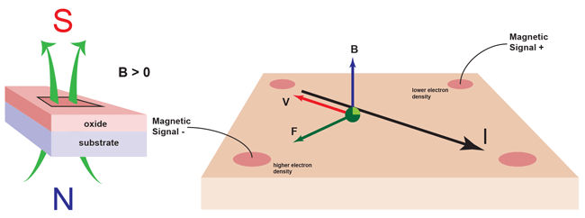
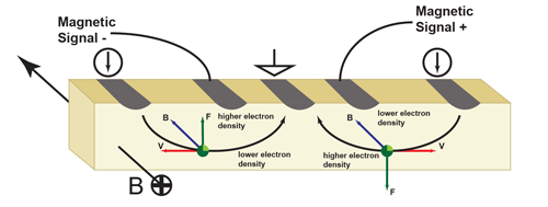
Planar Hall elements are constructed across the length and width of the die (in-plane) as shown in Figure 2. Vertical Hall elements are constructed from bottom to top along the depth of the chip as shown in Figure 3.
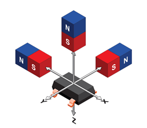
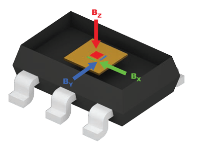
By rotating the IC, or by altering the orientation of the vertical Hall sensing elements on the die, a sensor IC can discriminate magnetic field direction as well as amplitude and truly sense in multiple spatial dimensions. In the A1262, the X and Y axes are the vertical Hall sensing axes, and the Z axis is the planar Hall sensing axis (See Figure 4).
There are two different sensing configurations of the A1262 that can be chosen as ordering options. The difference is the orientation of the vertical Hall element. The X-Z option has a vertical Hall element oriented in the X axis working in conjunction with the planar Hall element in the Z axis. The Y-Z option has the vertical Hall element rotated to be sensitive in the Y axis. This allows the user to choose how to position the sensor IC relative to the ring magnet. This is further explained in the Sensing Configuration section.
Sensing Configurations
The A1262 offers dual-channel sensing with ring magnet-independent output quadrature. It is offered with the option of two different 2D sensing axes configurations, the X-Z and the Y-Z axes. The vertical and planar Hall elements are used together to generate the dual outputs in quadrature, similar to using dual-planar sensor ICs like the A1230 or A3425 (however the dual-planartype sensors are sensitive in only one configuration). The planar Hall element positioned head-on to the ring magnet senses the magnetic poles, while the vertical Hall element senses the transitions between poles (as shown in Figure 12).
In the X-Z configuration (Figure 5), the Hall elements are positioned to detect magnetic fields parallel to the face of the package, across/perpendicular to the non-leaded sides (X axis) and magnetic fields perpendicular to the face of the package (Z axis), as shown in Figure 2. The vertical Hall can be configured to sense the magnet poles (head-on).
Since the sensor IC is sensitive on the edges without leads, the IC can be positioned closer to the target (compared to the Y-Z combination), in applications which require the IC to be oriented with the vertical element positioned head-on to the magnet (see Figure 7).
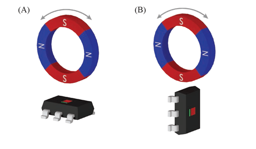
in conjunction with Z planar Hall element.
The Z-axis planar Hall (shown in red) can be employed head-on (A).
The X-axis vertical Hall (shown in green) can be employed head-on (B).
In the Y-Z configuration (Figure 6), the Hall elements are positioned to detect magnetic fields parallel to the face of the package across the leaded sides (Y-axis) and magnetic fields perpendicular to the face of the package (Z-axis). The vertical Hall can be configured to sense the magnet poles (head-on). Traditional dualchannel devices like the A1230 and A3425 cannot sense the ring magnet in either of the Figure 6 configurations (A or B).
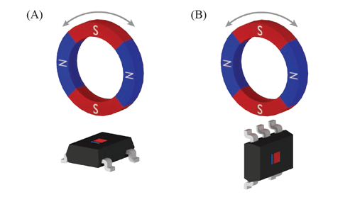
in conjunction with Z planar Hall element.
The Z-axis planar Hall (shown in red) can be employed head-on (A).
The Y-axis vertical Hall (shown in blue) can be employed head-on (B).
Close Air Gap Capability
The available X-Z option allows for extremely close air gap positioning of the sensor to the magnet for applications that require the PCB to be perpendicular to the ring magnet. This is due to the sensitive edges being the sides without leads.
Figure 7 illustrates the advantage of sensing on the side without leads. Sensing on the leadless sides allows the IC to be placed at the edge of the PCB, without the need to accommodate the device leads and the associated PCB solder pads and traces. This results in a significant reduction in Total Effective Air Gap (TEAG). On the Y-Z option the sensor must be placed further inboard on the PCB.
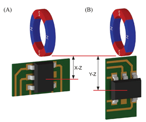
vs. Y-Z (B) configuration
Table 2: Sensing Option Part Numbers
| Y-Z Option | X-Z Option |
| A1262LLH-T | A1262LLH-X-T |
Dual Output
The A1262 is a dual-output sensor with outputs for the vertical Hall element (X or Y) and planar Hall element (Z) on two independent output pins (OUTPUTA and OUTPUTB, respectively). This is achieved with time-division multiplexing of the channels. See the block diagram in Figure 8. Each channel is sampled approximately every 16 μs (typical) to allow for channel settling, therefore both channels are updated approximately every 32 μs. See Figure 9.
The relatively fast time-division multiplexing of the A1262 sample rate is capable of high magnetic input frequencies, and is suitable to most applications. Contact your Allegro representative for more information regarding suitability to high frequency applications.
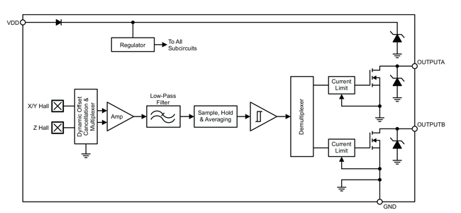
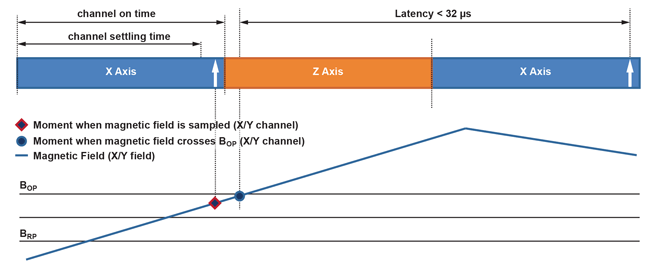
Respective outputs update after channel settling time.
Inherent Quadrature
With the planar and vertical elements located in essentially the same spot, this sensing technique alleviates the need for ring magnet target optimization to achieve quadrature (90° phase separation between output channels).
Dual-planar sensor ICs will only have the two channels in quadrature when the ring magnet pole-pair pitch is 4× that of the Hall element pitch.
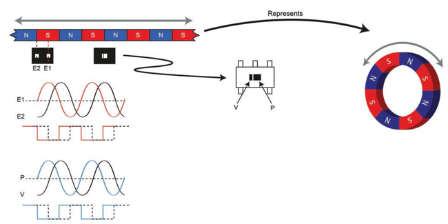
Figure 10 above shows a ring magnet with the magnet pole pitch dimension optimized for a dual-planar sensor IC, resulting in 90° phase separation in the output signals, while Figure 11 below shows a ring magnet with a significantly larger magnet pole pitch. This larger pole pitch is not optimized for the Hall element spacing of the dual-planar sensor IC, and results in a significantly smaller output signal phase separation. Since the 2D sensor IC is not affected by the magnet pole pitch, the output signals remain in quadrature (90° phase separation).
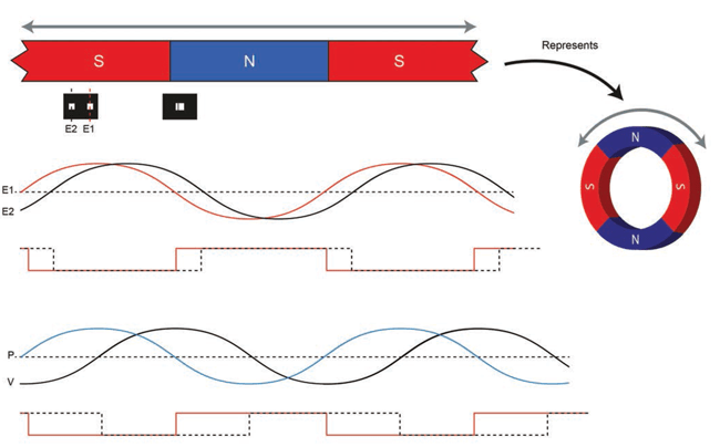
Figure 12 below illustrates how a 2D sensor array achieves quadrature sensing independent of the magnet dimensions.
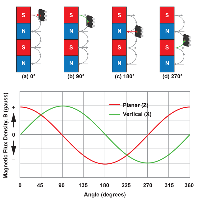
flux density) vs. ring magnet positions
- The IC is positioned over a south pole. In this position, the perpendicular flux is in the Z axis, and only passes through the planar Hall element, while there is no perpendicular flux in the X axis. Therefore the respective output channels will output a voltage proportional to the perpendicular flux. The Z channel will output a positive voltage, while the X channel will be at zero volts.
- The IC is positioned over the transition from south-to-north poles. Now the Z channel output will be zero and the X channel output will be a positive voltage.
- The IC is positioned over a north pole, resulting in the Z channel output to be negative, while the X channel is back to zero.
- The IC is positioned over the transition from north-to-south poles. The Z channel output is now zero again, while the X channel output is negative.
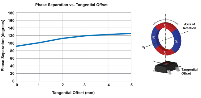
Phase Separation
Phase separation with the A1262 is inherently 90°, regardless of the magnet pole pitch. However, the mechanical placement can affect the phase separation.
As shown in Figure 13, when the sensor IC is not aligned with the axis of rotation (tangential offset), the phase separation can shift by several degrees from 90°. The amplitude of the shift in phase separation depends on the amount of mechanical offset. In this example, the effects are exaggerated due to the relatively large offset and a small diameter ring magnet.
Summary and Conclusions
The A1262 incorporates new vertical Hall sensing technology to provide an ideal solution for rotating ring magnet and motor applications. In comparison to existing dual-channel Hall latch ICs, designing with the A1262 is much easier with fewer constraints and more options for overall system configuration and mechanical packaging. The unprecedented flexibility offered by a 2-dimensional dual-channel magnetic sensor IC alleviates the need to optimize the ring magnet target for output quadrature, and, with a choice of two different vertical sensing axes, provides various options for IC and PCB mounting.
- The designer can choose any of four different sensing orientations, as well as chose between a surface-mount (LH) or through-hole package (K).
- 2D sensing provides inherent output signal quadrature, irrespective of the ring magnet design, providing the option to use existing ring magnets from other applications or to select an off-the-shelf ring magnet.
- The X-Z option provides improved TEAG versus legacy dualchannel devices including those offered in SOT packages.
- The ability to sense in-plane using a surface-mount device supports the design of smaller, lighter systems with fewer assembly steps versus legacy implementations using sensors in through-hole (SIP) packages.
For additional information of the Allegro A1262 2D Hall-effect sensor IC, please refer to the A1262 datasheet and other application notes available in the Allegro Design Center.