High-Current Measurement with Allegro Current Sensor IC and Ferromagnetic Core: Impact of Eddy Currents
Introduction
The technique of measuring bus bar current with a surrounding ferromagnetic core is common knowledge. For high current measurement above 200 A, Allegro recommends using a linear IC of the A136x family, such as the A1367, in conjunction with a magnetic core (Figure 1). This document focuses on alternating current (AC) effects on the current measurement. AC input currents tend to generate eddy currents in the magnetic core. These eddy currents alter the measured magnetic field and consequently decrease current measurement accuracy.
For more details about core design, refer to “Guidelines for Designing a Concentrator for High-Current Sensing Applications with an Allegro Hall-Effect Sensor IC” [1], available on the Allegro website.
Note that all results in this document come from electromagnetic simulations performed in Ansys Maxwell software.
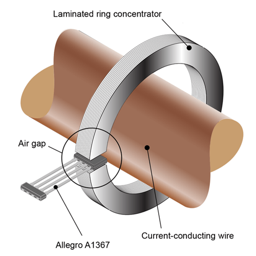
magnetic core and Allegro A1367
Measurement Principle
Ideally, the magnetic field, H, in the air gap is perfectly proportional to the input current, I, in the bus bar or currentconducting wire. Thus, it is enough to measure this magnetic field with a linear magnetic field sensor and to characterize the coefficient between the input current and the magnetic field to measure this input current. This coefficient, SC, is called the coupling factor or the core sensitivity. However, this coupling factor is only constant over a limited range of current and frequency. Any change of this coefficient leads to input current measurement error. Typical accuracy requirements are in the range of a few percent of the measured current.
Eddy Current Basics
Eddy currents are a direct effect of Lenz’s law which states that the direction and magnitude of the current induced in a conductor by a varying magnetic field is such that it creates a magnetic field
that opposes the change that produced it. In an AC current sensor application using a ferromagnetic core, eddy currents are induced inside the core as a response of the tangential varying magnetic field. Figure 2 shows a YZ cross section that schematically represents the eddy currents in a bulk core.
These eddy currents generate an induced magnetic field, Heddy, opposite to the exciting magnetic field, Hexc. This is measured at the sensor level as a reduced core sensitivity, SC , or otherwise
said, a current measurement error.
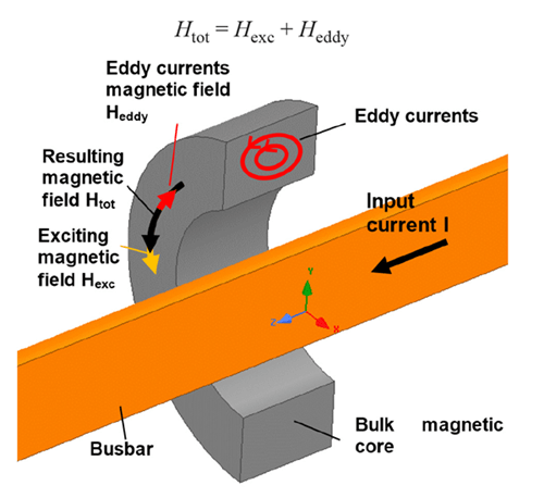
in a bulk magnetic core
In order to reduce eddy currents, it is necessary to cut the current paths in the core. This is achieved by using a laminated core with thin sheets. These sheets must be electrically isolated from each
other.
The lamination can be done in the Y direction by rolling or in the Z direction by stacking sheets (Figure 3). Eddy currents still flow, but with a reduced magnitude.
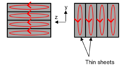
eddy currents: rolled (left) and stacked (right)
Typical Application Using Allegro A1367LKT Linear Sensor IC
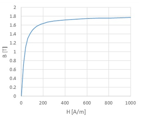
A typical high-current application using an Allegro A1367LKT linear sensor IC is considered here. Maximum peak current in this application is 600 A. The geometry is as given in Figure 4. The core length along the Z axis is 6 mm. The core is made of ferromagnetic material such as grain-oriented silicon steel with typical magnetic characteristics as in Figure 5. Initial relative permeability is 10000 and magnetic polarization at saturation is 1.8 T. Note that for the sake of simplicity, magnetic hysteresis is not considered. The core electrical resistivity is 45 μΩ/cm.

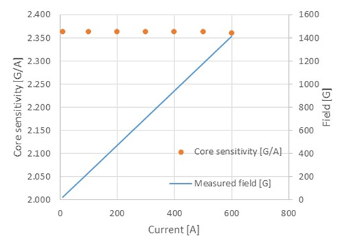
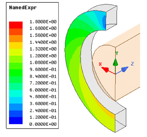
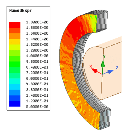
The DC core sensitivity, SC, is evaluated from 0 to 600 A. Figure 6 reports the expected measured field at the A1367 Hall plate location and the expected core sensitivity. The core magnetic sensitivity is constant up to the maximum current, as expected. The core sensitivity is around 2.36 G/A. In bipolar mode, the A1367 uses a ±2 V output span. Consequently, the IC sensitivity is ~1.4 mV/G, and the recommended A1367 part option would be A1367-LKTTN-2B-T. Figure 7 displays the core magnetization at maximum DC current; the magnetization
does not reach saturation.
Now, a sinusoidal current is supplied to the bus bar with a 600 A peak value.
Three cores are evaluated:
- Bulk
- Laminated with 0.375 mm sheets, along the Z direction
- Laminated with 0.250 mm sheets, along the Z direction
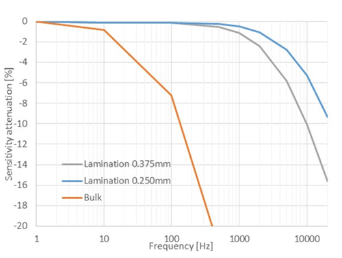
Figure 8 reports the magnetic core sensitivity attenuation δ over frequency. The attenuation, in percent, at frequency f is defined as:
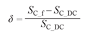
SC_f is the core magnetic sensitivity at frequency f. SC_DC is the core magnetic sensitivity in DC and 10 A. In a bulk core, the sensitivity decreases very quickly versus frequency: at 100 Hz, this is already significant (>5%). Otherwise said, a bulk core is only suitable for near DC measurements.
Laminated cores can be used up to a few kHz, depending on required accuracy. As expected, thinner sheets result in better AC performances.
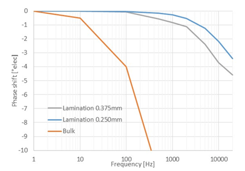
Figure 9 displays the phase shift between input current and the magnetic field measured in the air gap. Figure 9 indicates that the magnetic field measured by the IC is lagging the AC current
flowing in the bus bar. In a laminated core, this lag can be up to a few electrical degrees for current frequency above a few kHz.
As a direct consequence, an input current step could be measured with a significant delay because of its high harmonic content. Note that the attenuation and the lag are due to the eddy current
physics only. A perfect magnetic field sensor with infinite bandwidth would also see these effects.
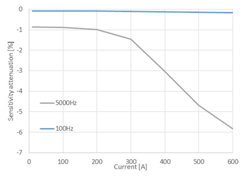
The attenuation versus the input current is reported in Figure 10 for a 0.375 mm sheet laminated core. A very interesting phenomenon is visible on this plot. At low frequency, the attenuation
is constant over the current, whereas attenuation drops around 300 A at 5 kHz. This can be explained by an early saturation of the core which is induced by the eddy currents. Below 300 A,
the attenuation is only due to the eddy current in the concentrator which works in the linear area of Figure 5. At 300 A, the eddy currents locally generate a high magnetic field that saturates the
core. Hence, the core magnetic sensitivity is already reduced at 300 A, while the core normally saturates at more than 600 A in DC. This is clearly visible while comparing the core magnetization
from Figure 7 and Figure 11. Note that the “noise” visible on the core magnetization mapping of Figure 11 is not real but due to the simulation mesh.
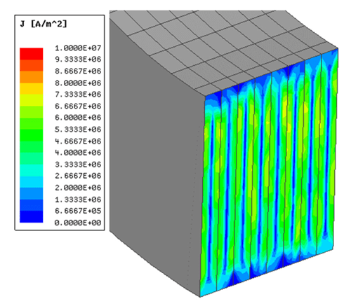
Figure 12 represents the eddy current magnitude density inside a section of a 0.375 mm laminated core at 5 kHz and 600 A.
vs. frequency at 600 A AC current
laminated core with 0.375 mm thick sheet
laminated core with 0.375 mm thick sheet
Conclusions
The analysis shows:
- Eddy currents induce a current measurement error due to an altered core sensitivity and a phase shift between the input current and the generated magnetic field.
- Eddy currents are reduced by core lamination: the thinner the sheets, the better the behavior over frequency.
- Bulk magnetic cores are only for DC measurements or very slow AC, roughly less than 10 Hz.
- Laminated magnetic cores are recommended for AC measurements for frequency up to a few kHz, with sheets of a few hundred μm and a required accuracy around a few
percent. - For a given application, the worst-case measurement error is at maximum application frequency and maximum application current.
Allegro engineers can assist customers to design the best magnetic core for their application depending on current and frequency range. Contact your local Allegro Microsystems technical
center for assistance.
Guidelines for Designing a Concentrator for High-Current Sensing Applications with an Allegro Hall-Effect Sensor IC”,
/en/insights-and-innovations/technical-documents/hall-effect-sensor-ic-publications/current-sensor-concentrator.