Achieving Fast SENT Message Response with A1346 Linear Hall-Effect Sensor ICs on Shared Bus
Introduction
In safety-critical magnetic sensing applications, such as torque sensing in electronic power steering (EPS) modules, redundant sensors are often the approach used to achieve desired performance while maintaining strict safety requirements. Dual-die linear magnetic sensor ICs, such as the Allegro A1346, package two sensors in a single, low-profile surface-mount device to save room on PCB designs. Along with the need for redundancy in the magnetic system and the desire for simple wiring harnesses with few wires is the requirement of a busable output protocol.
Building on the well-defined and widely used Single Edge Nibble Transmission (SENT) protocol, Allegro has developed the proprietary Sequential SENT (SSENT) and Addressable SENT (ASENT) options. Each of these options allow up to four devices to share the output line. This can be any four devices that also use the SSENT and/or ASENT protocols, such as Allegro angle sensor ICs, set to the same configuration. The option to bus the outputs together has the limitation of how quickly magnetic information and diagnostic information critical to achieve required safety ratings can be received. In this application note, the extended data nibbles are not considered, as these add the same duration to every SENT protocol and therefore do not affect the determination of the fastest SENT protocol.

Sequential SENT (SSENT)
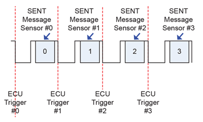
The SSENT protocol used in the A1346 is split into two options, short trigger mode (SSENT Short) and long trigger mode (SSENT Long). Both SSENT options require polling the sensors in sequential order, as seen in Figure 1. The difference between these two options is how it handles function pulses, or triggers, of certain lengths. With both protocols, the host controller must pull the output line low for a set length of time to tell the sensor IC to either send the magnetic data, perform a diagnostic test, latch magnetic data, or resynchronize its counter. SSENT Long mode allows for a larger range of F_OUTPUT pulse (SENT trigger) lengths to allow for SPC compatibility. This allows a shorter trigger to be used to request the SENT message, resulting in a faster total message time.
Table 1: SSENT Function Pulses in Short Trigger Mode, outmsg_mode = 4
| Function Pulse | Minimum Number of Ticks | Maximum Number of Ticks | Function |
| F_OUTPUT | 15 | 19 | Triggers the SENT message on the device output. |
| F_SAMPLE | 31 | 39 | Triggers sensors to latch magnetic data, but not send the SENT message. |
| F_DIAG | 56 | 70 | Triggers device self diagnostic. |
| F_SYNC | 93 | 115 | Resets the Sensor counter to count 0. |
Table 2: SSENT Function Pulses in Long Trigger Mode, outmsg_mode = 3
| Function Pulse | Minimum Number of Ticks | Maximum Number of Ticks | Function |
| F_OUTPUT | 9 | 81 | Triggers the SENT message on the device output. |
| .F_SYNC | 105 | 171 | Resets the Sensor counter to count 0. |
| F_DIAG | 216 | 264 | Triggers device self diagnostic. |

The SSENT options are highly configurable to accommodate a wide range of system requirements. One available option is slot marking. This option adds a specific length high period delay before the start of the SENT synchronization pulse, its length determined by the Sensor ID of the sensor that responds. This is commonly used to add robustness to the protocol by allowing the sensors to resynchronize their counters based on the slot marking pulse that is seen, allowing sensors to return online without host controller intervention. See A1346 datasheet for more information.
While the slot marking option can provide increased robustness of the output line, in the case of sensor outputs being disconnected, Allegro does not recommend using this option for tick times less than or equal to 1.22 μs, since the delay time associated with the Sensor ID might be too short for the sensor to process and give out the new sample. When there is a desire to produce the SENT output as fast as the system will allow, slot marking causes a tick time limitation. Because of this, the option to use slot marking is not considered in this application note.
Addressable SENT (ASENT)
Unlike the SSENT protocol, where the sensors must be polled in sequential order, the ASENT protocol in the A1346 allows for random polling of the sensors. This makes the protocol more robust for when the sensors handle going offline and allows for more flexibility in sensor sampling. This robust nature of the protocol comes at a cost of additional message length. For it to be clear which sensor is being polled, the function pulse is accompanied by an addressing pulse consisting of a 7 tick high period followed by the 5 tick low period. This is incremented for each sensor address, with sensor 1 (address 0) having none of these pulses, sensor 2 (address 1) having one of these pulses, etc., as shown in Figure 2. This can add up to 36 additional ticks to the message length for the sensor with address 3, resulting in a tradeoff between the robust data bus and possible message polling rate.
Table 3: ASENT Function Pulses, outmsg_mode = 5-7
| Function Pulse |
Minimum Number of Ticks |
Maximum Number of Ticks |
Function |
| F_OUTPUT | 15 | 19 | Triggers the SENT message on the device output |
| F_SAMPLE | 31 | 39 | Triggers sensors to latch magnetic data, but not send the SENT message |
| F_DIAG | 56 | 70 | Triggers device self diagnostic |
Output Mode for Fastest Message Rate
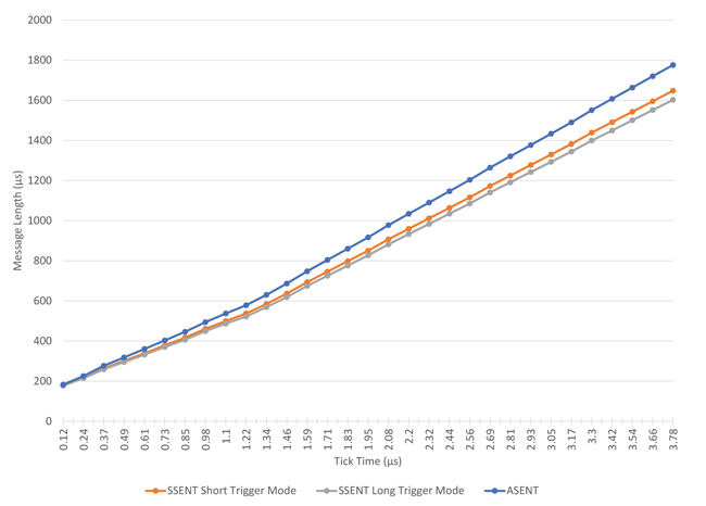
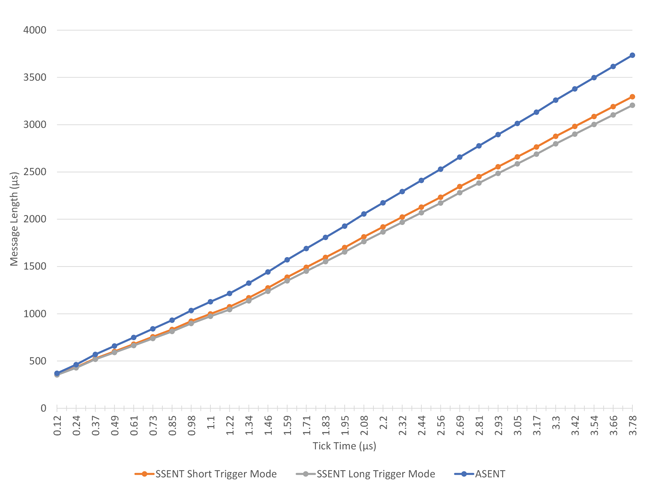
It can be seen from both Figure 3 and Figure 4 the output protocol with the shortest total message transmission time is the SSENT Long option. This option is achieved with outmsg_mode = 3 (address 0x14 bits [2:0]). The shortest possible trigger length for this mode is 9 ticks, allowing it to achieve a faster data rate than the SSENT Short mode, which requires a 15 tick minimum trigger. This mode is also compatible with controllers that may require the use of longer triggers, making it an ideal choice for magnetic data transmission.


Conclusion
In safety-critical applications, such as torque sensing in EPS applications, redundancy of devices is often not only desirable, but required. To save space and cost in the harness connecting the sensors to the host controller, having the different sensors connected to a single output bus is becoming increasingly popular. To maximize performance, the magnetic data should be polled as fast as possible to allow for external processing. The three proprietary, busable output modes on the A1346, SSENT Short, SSENT Long, and ASENT, each have their strengths and weaknesses in balancing speed, complexity, and sensor communication robustness.
When the main concern is how quickly the magnetic data can be received, the A1346 output protocols all feature proprietary fast SENT tick times that greatly reduce the total message time over the standard SENT protocol. Due to not needing the addressing pulses, SSENT in either long trigger or short trigger mode will always result in receiving the magnetic data in the shortest amount of time among these proprietary output modes. Of those two modes, SSENT Long produces the shortest overall time due to a shorter minimum trigger time, saving 6 ticks for each sensor. The use of the proprietary fast SENT options available in the A1346 gives the sensor the ability to deliver accurate magnetic data from multiple sensors to the electronic control unit at a high frequency on a single output line, enabling high performance, and low system cost and complexity.