EV Traction Motor Requirements and Speed Sensor Solutions
Abstract
Vehicles that use traction motors are becoming increasingly popular all over the world. This paper explores the general requirement trends for speed and position sensors in traction motor systems, including high-speed capability, accuracy at startup, low-speed operation, immunity to vibration, EMC robustness, and safety. Allegro MicroSystems provides several solutions to meet these requirements as well as other end-user requirements.
General Trends in Traction Motors
As the market moves towards making electric vehicles more widely available, two key factors will impact how requirements develop for existing traction motor systems:
1. Reducing Cost: Bringing the entry cost of electric vehicles in line with internal combustion engine vehicles.
2. Increasing Range: Enabling battery electric vehicles (BEV) and plug-in hybrid electric vehicles (PHEV) to be viable options to a broader market.
These factors will continue to push manufacturers to search for solutions that both increase performance and use more cost-effective EV motor solutions.
Evolving EV Motor Requirements
High-Speed
Unlike internal combustion engine (ICE) vehicles, electric vehicles typically either do not have transmissions or have low gear-count transmissions. Traction motors used by electric vehicles are required to operate efficiently over a wide range of speeds; thus, one or two gear ratios is all that is required most of the time. The lack of transmission gearing requires traction motors to operate at higher rpms than combustion motors. This presents a new set of technical requirements against which sensing devices must perform.
While typical combustion engines will start to redline at around 6,000 rpm, many traction motors can operate far beyond this. It is common to find EV motors that turn almost two or more times faster than ICE motors. For example, the Chevrolet Bolt EV, which has been on the market since 2016, uses a traction motor with a maximum speed of 8,810 rpm. This is an improvement from the Chevrolet Spark EV (2013 – 2016), a predecessor to the Bolt, which used a motor with a maximum speed of only 4,500 rpm [1]. The Nissan Leaf, a comparable vehicle to the Bolt, uses an EM57 traction motor with a maximum speed of 10,390 rpm.
Higher performance electric vehicles like the Tesla Model 3, require even greater rpms. It is estimated that the Model 3 engine can reach up to 27,200 rpm [a] at a top speed of 162 mph. The Model 3 is one of the most popular electric vehicles of the past few years, so there is a clear desire for high-performance electric vehicles. It is likely in the future there will be an increase in demand for traction motors capable of reaching speeds like the Model 3. Semiconductor sensing elements must be redesigned to meet these new high-speed high-performance applications.
Startup, Low-Speed, and Vibration Requirements
Startup
The startup requirements of traction motors vary dramatically depending on the type of motor involved. Most automotive traction motor applications use either a permanent magnet synchronous motor (PMSM) or an induction motor (asynchronous motor). Each motor has different features, as well as different sensing element requirements.
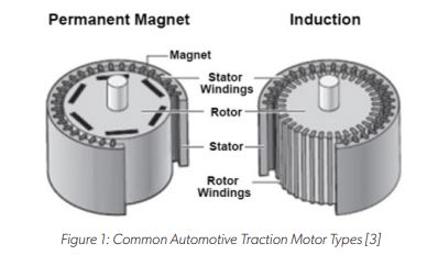
Permanent Magnet Synchronous Motors
Applications using a permanent magnet synchronous motor require feedback solutions that provide absolute rotor position at startup. This is critical for the initial startup, as synchronous motors operate with the stator and rotor “in-phase”. Error of the rotor position feedback at startup can result in an unintentional phase of the drive to the motor. This will cause the rotor to accelerate and/or “jerk” to match the initial phase of the motor drive, possibly in the opposite direction of the intended drive.
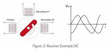
Existing solutions used to meet the needs of permanent magnet synchronous motor commonly include the absolute position encoder or the resolver. Resolvers have become the more dominant solution in the market due to their reliability in the harsh automotive application space, being generally more resistant to electromagnetic disturbances and high temperature.
Induction Motors
Applications using an induction motor are not bound by the same absolute position feedback requirements at startup as the permanent magnet synchronous solutions. As there is no direct phase matching between the rotor and stator required at startup, the rotor will follow any given stator phase provided at startup.
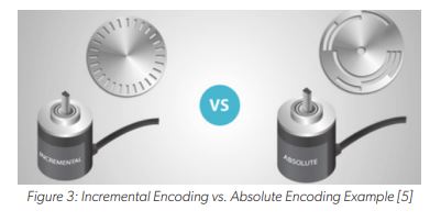
Existing solutions used to meet the needs of induction motors commonly use the resolver or incremental position encoder. Incremental position encoders offer little to no information at startup (which is acceptable for an induction motor), but also provide a cost savings over the resolver and their absolute position counterpart. While it is unnecessary to provide absolute position at startup, resolvers are still commonplace in applications using induction motors for the added reliability provided.
Low-Speed
Low-speed performance is critical for traction motors. As lower speeds are a low-efficiency mode for most traction motor systems, any additional losses due to poor motor control must be mitigated. Additionally, for autonomous systems being developed for use with traction motors, such as self-parking and Tesla’s “Smart Summon” feature, higher resolution in the feedback of these motor control systems is required.
While analog sensing solutions, such as resolvers, have effectively infinite resolution themselves, the traction system is still bound to the resolution limitations of the controller’s ADC and the noise of the system. Increasing the number of bits in the ADC (to the extent bound by the noise in the system) and reducing the system noise will produce higher resolution.
Digital sensing solutions, such as the encoder solutions, have the resolution built in to the number of sensed output transitions per revolution. Increasing the number of sensed features of the target will increase the resolution of the system.
Vibration
Like startup and low-speed, sensor and controller response to vibration events play a large part in the performance in traction motor systems. There are many forms of vibration within a traction motor system, all producing potential error if not sensed and/or handled properly. This potential error can impact the feedback loop of the control system to varying degrees, ranging from a minor and temporary error in the angle to a miscalculation of the rotor position entirely, resulting in improper drive to the motor and a safety-critical failure. Mitigation of the effects due to vibration in control systems largely depends on the sensing solution used. Therefore, sensors have been designed with algorithms to achieve the desired performance without causing a failure. While seemingly a new advance in technology, vibration algorithms have been around for a long time in specialty applications such as transmissions and crankshaft sensors.
Resolvers and absolute position encoding sensors are extremely robust to vibration events. Today, sensors process and remove errant signals from vibration events and provide valid signals to the controller. There is no need for prior knowledge for the feedback system to function properly, and no additional requirements are needed by the controller for recovery after vibration events for these solutions. During vibration events, the response of the system is entirely dependent on the controller, as the sensor will continue to output an accurate position of the rotor at each sample.
Incremental position encoders can be susceptible to missing and/or extra tooth counts on vibration events, requiring more sophistication in the sensor and in the controller to mitigate the effects due to vibration. Should a missing or extra tooth count occur, the sensor and/or controller can compensate for this to varying degrees depending on the severity of the vibration and the error of the count; otherwise, rotor position can be incorrect to an unknown degree until an index or synchronization signal is identified (usually once per revolution).
Market Trend Analysis: Startup, Low-Speed, and Vibration
To meet the market needs of reducing cost and increasing range, it can be expected that the permanent magnet synchronous motor will continue to be the popular choice for traction motor solutions, as made evident by Tesla designing-in their first synchronous motor solutions in the Model 3. Despite Tesla’s longstanding history championing the induction motor solution, the change to the synchronous motor was necessary for the Model 3 [b] to meet the overall requirements of cost and efficiency.
With the continued trend of permanent magnet synchronous motors used for electric vehicle traction systems, coupled with an increased push to reduce costs, manufacturers will continue to look for alternative solutions to the existing high-cost resolver and absolute position encoders offered today.
Additionally, solutions will need to meet a high-resolution output requirement and have robust algorithms in the sensor and/ or controller to meet an increasing need to be robust against vibration events, particularly with an increase in functional safety requirements.
Electromagnetic Compatibility (EMC) Requirements
EMC requirement can vary depending on the application, component, region, etc. The general trend is that over time, EMC robustness is becoming a more critical and stringent requirement from OEMs to tier 1 and tier 2 suppliers. This is particularly true of the traction motor market. As sophisticated systems are developed, more requirements are being demanded of the components used in those systems to be immune to stray electromagnetic fields and to withstand enhanced voltages, currents, and other electromagnetic signals. Additionally, these systems, and the components contained therein, will need to adapt to strict requirements for emissions given the increased electrification of the applications for traction motor systems.
As demand for more cost-effective and efficient traction motor systems develop, more high-voltage systems will develop. This will require components to be rated to withstand much higher voltages than previous generations, equivalently suited for internal combustion engines or other single-battery/low-voltage applications.
Reliability, Functional Safety and ASIL Requirements
Functional safety is becoming increasingly important in the automotive industry. Most OEMs follow the ISO 26262 standard which defines the Automotive Safety Integrity Level (ASIL) classification system. Using the ISO 26262 standard ensures reliability and failure management over the lifetime of a vehicle. The four levels in ASIL ranging from lowest to highest level of risk are A, B, C, and D. As more self-driving vehicle enter the roads there is a greater need for vehicle systems to adhere to stricter safety requirements, and most systems will require a level D decomposition.
Allegro Solutions Meeting the Needs of Traction Motor Trends
ATS17501/A17501: Dual Output Differential Speed and Direction Sensor IC
Overview
The ATS17501/A17501 is a single integrated circuit (IC) solution designed for rotational position sensing of a ferromagnetic gear or ring magnet target commonly found in traction motor systems. The ATS17501 is housed in a 4-lead SIP (“SG” package) that incorporates a rare-earth magnetic pellet for ease of manufacturing, consistent application performance over temperature, and enhanced reliability (see Figure 4). The A17501 is housed in a 4-lead SIP (“K” package) which can be used to sense a ring magnet or a ferromagnetic target when properly “back-biased” with a magnetic pellet (see Figure 4).

Three Hall elements are incorporated in the IC to create two independent differential magnetic sensing channels in the sensor IC. These inputs are processed by digital IC circuits and robust algorithms designed to eliminate the detrimental effects of magnetic and system offsets, and to address false output transitions caused by target vibrations at startup and low-speed operation that commonly occur in traction motor systems. The differential signals are used to produce a highly accurate speed output and, if desired, provide information on the direction of rotation.
Advanced calibration techniques are used to optimize signal offset and amplitude. This calibration, combined with digital tracking of the signal, results in accurate switch points over air gap, speed, and temperature.
The sensor IC can be programmed for a variety of applications requiring dual-phase gear speed and position signal information or simultaneous high-resolution gear speed and direction information.
Implementation for Incremental Position Sensing
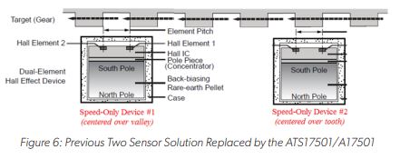
The ATS17501/A17501 can be used to track the position of a rotating gear by using ABZ encoding. The dual outputs are capable of producing both Channel A and Channel B signals in quadrature. The index or channel Z signal is typically produced by a separate sensor. These signals can be used to determine the speed and direction of rotation of the target.
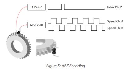
Previous sensing solutions required two sensors to achieve the Channel A and Channel B quadrature signals. Using the ATS17501 or A17501 reduces overall system cost and complexity by reducing the number of sensors, wires, and harnesses.
Benefits of ATS17501/A17501 for Traction Motor Applications
High-Speed
The ATS17501/A17501 is ideally suited for traction motor applications. The sensor IC can operate at up to 40 kHz, which meets the growing need for high-speed switching of traction motors.
Start-Up Performance/Algorithms
Selectable algorithms are used for determining when to produce an output transition from the magnetic input signal. For all options, a threshold is set within the ATS17501/A17501 that triggers the output transition when crossed by the digitized magnetic signals (switch point). When the sensor IC is programmed to use the “Fixed Threshold” option, an absolute threshold is stored in nonvolatile memory to set the switch point for both the operate point and the release point. This algorithm allows for accurate output transitions immediately after power-on for consistent magnetic input signals without the need to “learn” the signal. The threshold stored in memory and loaded during power-on contains threshold levels over temperature to allow for offset drift adjustment of the magnetic input signal over temperature. The sensor IC contains a temperature sensor used continuously to adjust the switch point over temperature as needed by the application. The sensor can also be programmed to use the “Dynamic Threshold” option, where each switch point is calculated from information learned about the previous target feature. This algorithm allows for robust tracking to produce accurate output transitions for inconsistent magnetic input signals (offset drift, amplitude changes, etc.). Additionally, the sensor can be programmed to use the “Hybrid Threshold” option where the threshold is determined from the Fixed Threshold option at startup, then transitions to the Dynamic Threshold option after tracking signals have correctly acquired the magnetic input signals.
The ATS17501 and A17501 also contain algorithms that can counteract the negative effects of vibration in traction motor systems. When a direction change occurs, inward bounding of the peak tracking signals is suspended to prevent erroneous output transitions from switch points being incorrectly set from vibration signals. Additionally, this allows for immediate acquisition of the magnetic input signals once real target rotation resumes following a vibration event.
EMC Robust
The ATS17501/A17501 contains an on-chip regulator and can operate over a wide range of supply voltages. When proper external components are used, the sensor shows robust EMC performance.
Safety/ASIL
The ATS17501/A17501 contains diagnostics monitors of analog and digital circuits of the sensor IC. When Fault Detection Mode is enabled, these continuously monitor and report if any defect, calculation error, or invalid input stimulus is found. If a diagnostic monitor fires, the sensor IC can communicate a fault through the voltage level of the outputs. For all faults, the outputs will remain at the fault voltage level for enough time to allow the system controller to monitor that a fault has occurred. For some diagnostics, it is possible to clear the fault with a reset of the internal controller of the sensor IC. If any of those diagnostic monitors triggers the fault event, the sensor IC will automatically perform a reset of the internal controller after the output is held at the fault voltage for enough time to allow the system controller to monitor the fault event. Enabling Fault Detection Mode allows for additional communication for cases of open wire or short circuit. When Fault Detection Mode is enabled, the sensor IC can be used in an ASIL B(D) level system. An ASIL D system can be achieved by using multiple sensors.
Continuous Improvement
Allegro is dedicated to continuous improvement to offer innovative products that meet the ever-evolving needs of the traction motor market. Allegro continuously designs, tests, and releases new products with improved features. Contact Allegro for the most up-to-date product information and availability.
Bibliography
[1] Kane, Mark. Deep Dive: Chevrolet Bolt Battery Pack, Motor And More. Retrieved from https://insideevs.com/news/329695/ deep-dive-chevrolet-bolt-battery-pack-motor-and-more/
[2] Nissan Leaf Gen1/2 Powertrain Information. Retrieved from https://www.motorreviewer.com/ev_powertrain.php?id=1
[3] Detloff, Cieana. AC Induction Motors vs. Permanent Magnet Synchronous Motors. Retrieved from https://empoweringpumps.com/ac-induction-motors-versus-permanent-magnet-synchronous-motors-fuji/
[4] How does a resolver work? Retrieved from https://www.celeramotion.com/zettlex/resolvers/
[5] Anderson, Mondi. Difference Between Absolute and Incremental Encoders? Retrieved from https://realpars.com/absolutevs-incremental-encoder/
[6] Ruoff, Christian. Tesla’s top motor engineer talks about designing a permanent magnet machine for Model 3. Retrieved from https://chargedevs.com/features/teslas-top-motor-engineer-talks-about-designing-a-permanent-magnet-machine-for-model-3/
Copyright 2022, Allegro MicroSystems.
The information contained in this document does not constitute any representation, warranty, assurance, guaranty, or inducement by Allegro to the customer with respect to the subject matter of this document. The information being provided does not guarantee that a process based on this information will be reliable, or that Allegro has explored all of the possible failure modes. It is the customer’s responsibility to do sufficient qualification testing of the final product to ensure that it is reliable and meets all design requirements.
Copies of this document are considered uncontrolled documents.