Have Questions? Let us help!
We're passionate about innovation. Reach out and you'll hear back from an expert shortly.
One of our solution experts will be in touch with you shortly. Keep reading to learn more about our industry leading solutions.

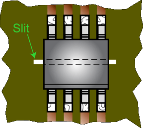
For the ACS712 and ACS713, the key limitation is actually the creepage and clearance distance inherent in the SOIC8 package. To achieve higher isolation voltage ratings, steps must be taken in the applications themselves, such as adding a slit on the circuit board underneath the device to increase the creepage distance, and possibly adding a conformal coating to increase the clearance distance. Because these solutions are a function of the PCB layout and the coating compound used, if a safety isolation standard is to be met, it must be certified at the application level.
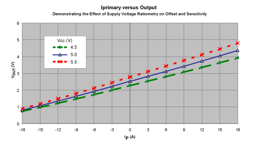
The ratiometric feature of the ACS714 and ACS715 means the device gain and offsets are proportional to the supply voltage, VCC. This feature is particularly valuable when using the ACS714 and ACS715 with an analog-to-digital converter. A-to-D converters typically derive a reference voltage from the A/D VCC voltage rail input. If the A/D VCC voltage varies, then the reference varies proportionally. One advantage of ratiometry is, if the reference voltage and the supply voltage for the ACS714 and ACS715 are derived from the same source, then both the ACS714 and ACS715 and the A-to-D converter track those variations, and such variations will not be a source of error in the analog-to-digital conversion of the ACS714 and ACS715 output. Below is a plot of primary current, IP, to output voltage, VOUT, of the ACS714 and ACS715 when varying VCC. The offset and sensitivity levels shift proportionally with VCC. For example, when VCC = 5.5 V, the 0 A output is 5.5 / 2 = 2.75 V nominal, and the sensitivity is 110 mV/A nominal.

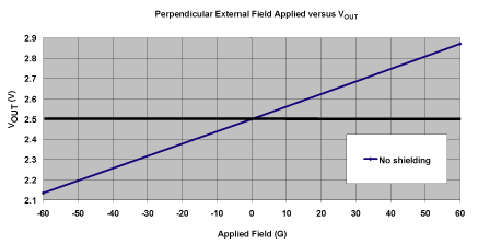
The magnetic coupling of the ACS714 and ACS715 is listed in the datasheets with a nominal value of 12 G/A. What this means is, for every ampere of current, 12 G of field is produced at the Hall element. For stray fields, the effect on the device can be calculated by dividing 12 G/A by the mV/A sensitivity of the device in use. This allows you to predict the Gauss per millivolt change at the output. The susceptibility of the ACS714 and ACS715 to external fields can be mitigated via proper orientation, spacing from external field sources, and if necessary, shielding of the device.


