Joystick with Allegro Position Sensor IC
By Christophe Lutz and Andrea Foletto,
Allegro MicroSystems Europe LtdIntroduction
Joysticks are widely used human–machine interfaces (HMI)that simultaneously report information on direction and amplitude. Stick tracking is realized by use of a magnet and a magnetic
position sensor.
This document explains how to implement a 2D or 3D magnetic sensor to obtain a joystick with a well-defined behavior. This note provides insights on two tracking methods: direct tracking and ratio tracking. Direct tracking offers a straightforward implementation, while ratio tracking offers excellent robustness to stick mechanical play. Finally, this application note assesses the relative robustness of these techniques to parameter variations (mounting and in-life).
Joystick Description
Mechanically, a joystick consists of a stick that pivots through a ball joint on its base. Figure 1 provides a cross-sectional view of a joystick.
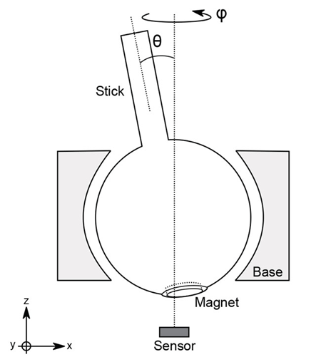
To track the position of the stick, a magnet is integrated on the bottom of the ball in order that the ball and magnet move as a unit when the stick is actuated. A magnetic position sensor should be placed beneath the magnet at a suitable distance, denoted as air gap.
Stick Tracking
Action on the stick of a joystick will affect the magnetic field as sensed by the sensor. In this application note, the magnetization of the magnet is axial and pointing down (south pole up, north pole down). The information of stick position is contained in the sensed magnetic field in x and y directions, as indicated in Figure 2.
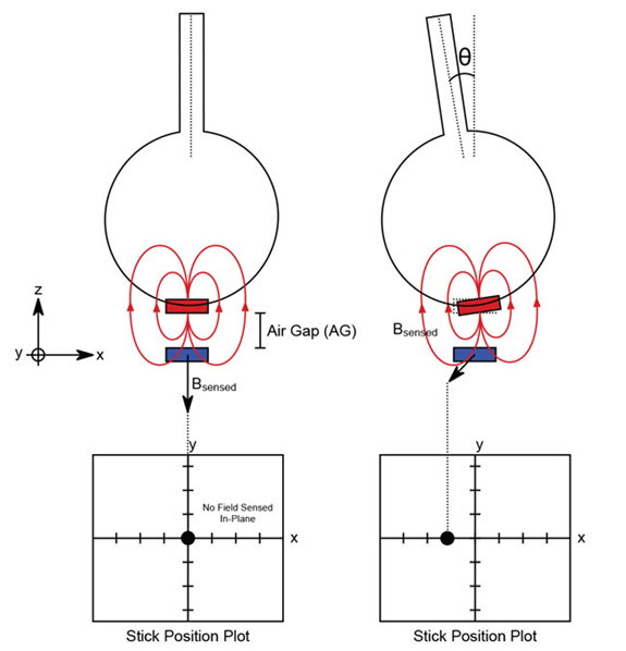
Increasing the tilt of the stick increases the sensed signal, since the in-plane magnetic field components are increased. To focus on the responsivity of the joystick with respect to the tilt, θ, it is convenient to exclude directional information.
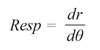
The stick position point in the position plot (represented by a black dot) is expected to move according to the tilt angle and in the same direction as the stick. Responsivity, Resp, shall be considered the distance from the stick position point to the center, as shown in Figure 3 and expressed as:
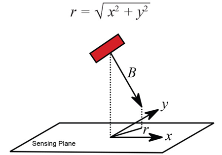
r can represent x (when φ = 0°) or y (when φ = 90°) or any combination of both when the direction is arbitrary. The responsivity of the stick position point in the position plot is defined as:
In practice, responsivity is also dependent on the orientation of the stick, φ, but this dependence can usually be excluded with respect to other parameters such as air gap.
As will be demonstrated in the next section, responsivity is closely related to the distance from the magnet to the sensor since it can exacerbate or dampen magnet border effect, short-scale
asymmetry, etc. This distance is commonly called air gap (AG).
For joystick applications, air gap is defined at no tilt, θ = 0°.
Air Gap Constraints
Air gap as defined in Figure 2 is a key parameter in the application that will both affect the selection of sensor and the final responsivity of the stick. This parameter must comply with the following mechanical and magnetic constraints.
Mechanical constraints will provide a lower bound to the air gap for a cylindrical magnet that is not embedded in the ball of the joystick. This constraint ensures no contact between the rotating
part and the sensor.
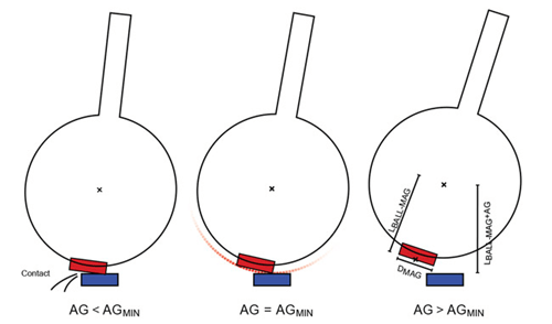
Minimum air gap, AGMIN(MECH) can be deduced by considering the limit contact case in Figure 4.
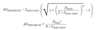
The mechanical lower bound should be considered when using a low sensitivity device.
Magnetic constraints arise from the signal level requirements. The sensor is typically able to sense a given range of magnetic field without experiencing saturation. For correct behavior, it is important to ensure the sensor does not saturate during implementation. In practice, this non-saturation condition provides an additional constraint on air gap, AGMIN(MAG), depending on the sensitivity of the sensor, the shape and remanent magnetic field of the magnet, and the maximum tilt angle, θMAX. When considering a joystick consisting of a ball joint of 10 mm diameter, a cylindrical magnet of 1 T, diameter 5.4 mm, length 1 mm, and which can be tilted of θMAX = 25°, simulations lead to the minimum air gap values shown in Table 1.
Table 1: Joystick Magnetic Limitations on Air Gap
| Sensing Range (G) |
AGMIN(MAG) | |
| No Saturation on x/y | No Saturation on z | |
| ±500 | 1.5 mm | 2.1 mm |
| ±1000 | 0.9 mm | 1.1 mm |
| ±2000 | 0.5 mm | mechanically limited |
Generally, for joysticks that use only small tilt angles (θMAX ≪ 25°), the non-saturation constraint is more restrictive on the z-axis with respect to the x/y axes. For this purpose, Allegro has developed sensors such as ALS31300 with a different sensing range on the z axis.
Since the air gap sets the level of the signal, it defines the signalto- noise ratio (SNR). The application defines a minimum value of SNR which consequently defines an upper bound to the air gap, AGMAX(MAG).
Note: A safety margin should be considered to ensure the air gap stays within its allowed range despite any parameter variation due to fabrication, lifetime drift, etc.
Direct and Ratio Stick Tracking
As mentioned previously, stick position information is contained in the sensed magnetic field on the x and y axes.
Direct stick tracking plots stick position by using the data sensed in x and y directly. The simplicity and general accuracy of this technique is sufficient for most applications. Its major drawback is its vulnerability to dynamic air gap variations that may occur during the lifetime of the product. This variation is typically from vertical play of the stick. For instance, pressing on the stick may cause the stick position point in the position plot to jump to another value. A dynamic air gap reduction will always lead to an increase of the magnetic field sensed.
To counter this unwanted effect, the ratio stick tracking technique can be implemented. The values sensed on x and y will more or less have the same change as the value sensed on z-axis when air gap varies. Thus, using x/z and y/z instead of solely x and y will significantly decrease air gap dependence. Although ratio stick tracking is more robust, it does influence the responsivity curves.
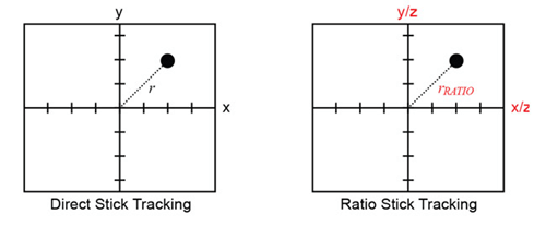
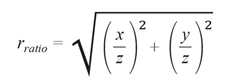
This transformation simply rescales the position plot (see Figure 5). All results contained by direct stick tracking can be straightforwardly translated to ratio stick tracking by substituting x (respectively y) by x/z (respectively y/z). As an example, the distance from the stick position point to the center of the position plot becomes:
Because of this, all joystick corrective behavior post-processing can be applied to both tracking methods. The difference in responsivity and relative robustness to variations differentiates the two tracking methods.
Responsivity of the Joystick
Responsivity of the joystick describes the correlation between the mechanical movements of the stick and its stick position point on the position plot as output by the sensor. The air gap affects this relationship.
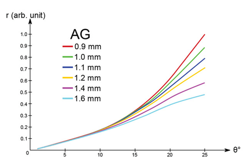
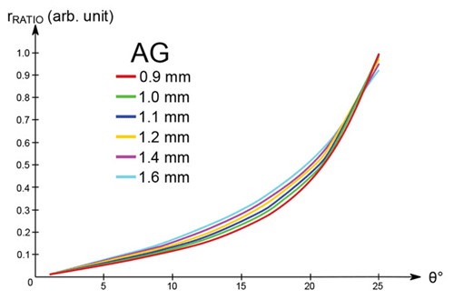
To explain the effect of the air gap, simulation for a joystick made of a ball joint of 10 mm diameter, a cylindrical magnet of 1 T, diameter 5.4 mm, length 1 mm, and which can be tilted of θMAX = 25°, gives results as shown in Figure 6 and Figure 7 for direct and ratio stick tracking, respectively.
From Figure 6, the following properties of direct tracking can be deduced:
- Large air gap leads to almost linear response over the tilt angle range.
- Low air gap leads to a joystick that responds linearly with small θ angles while the characteristic becomes nonlinear for large angles. This feature is interesting in application requiring both precision and range (high responsivity at high angle).
versus Air Gap
From Figure 7, the following properties of ratio tracking can be deduced:
- The effect of the air gap has been tremendously decreased as shown by the superposition of the curves.
- Regardless of the air gap, the joystick response is linear for small θ angles, while the characteristic becomes nonlinear for large angles. This feature is interesting in application requiring both precision and range (high responsivity at high angle).
The response curve nonlinearity is due mainly to the nonlinearity of the magnetic field with position and not to the sensing of the sensor. Nonlinearities can be neglected for small values of θMAX.
Joystick Robustness to Variations
The air gap addressed from previous considerations (constraints and behavior), the position of the sensor is fully determined.
Now, the two tracking techniques can be confronted in terms of their robustness against variations due to:
- Mounting precision
- Mechanical play
Due to physical limitations, the sensing elements of multi-axis position sensors cannot sense the magnetic field components at the exact same location. This tiny built-in asymmetry leads to different responses in different directions. Likewise, error plots may reflect this asymmetry.
The following parameters drifts have been considered:
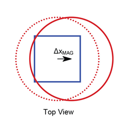
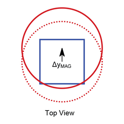
- Sensor displaced with respect to the stick axis.
- Magnet displaced with respect to the stick axis.
- Air gap smaller or larger with respect to its reference value.
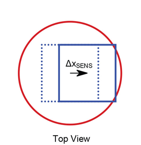
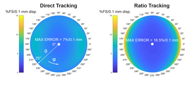
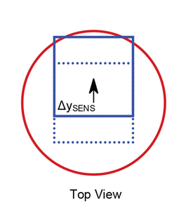
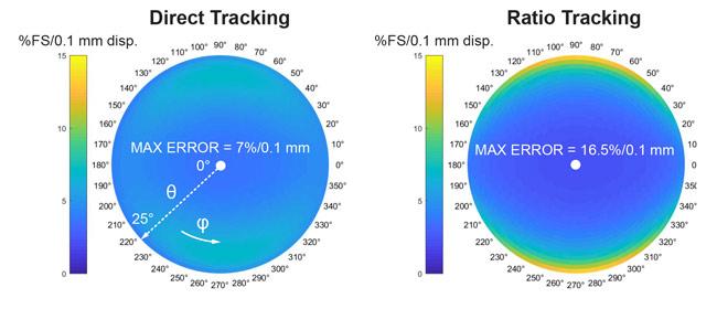
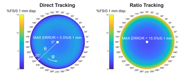
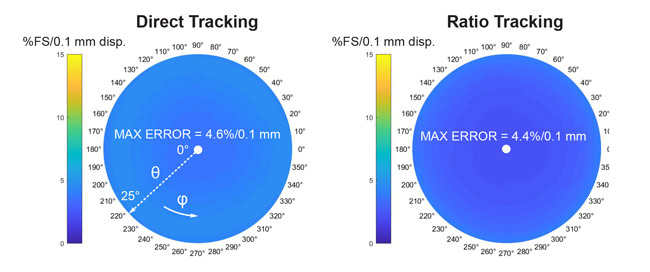
The error is quantified as the distance between the ideal and drifted position of the stick position point. To compare direct and ratio stick tracking techniques, their errors have been respectively expressed as a percentage of their full-scale (FS) values, namely rMAX and rRATIO(MAX).
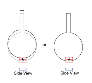
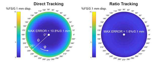
Figure 8: Air Gap Variations with respect to its Nominal Position
Simulation Assumptions: Ball joint of 10 mm diameter, air gap of 1.2 mm, cylindrical magnet of 1 T, diameter 5.4 mm, length 1 mm, and θMAX = 25°.
Simulation Assumptions: Ball joint of 10 mm diameter, air gap of 1.2 mm, cylindrical magnet of 1 T, diameter 5.4 mm, length 1 mm, and θMAX = 25°.
Simulation Assumptions: Ball joint of 10 mm diameter, air gap of 1.2 mm, cylindrical magnet of 1 T, diameter 5.4 mm, length 1 mm, and θMAX = 25°.
Simulation Assumptions: Ball joint of 10 mm diameter, air gap of 1.2 mm, cylindrical magnet of 1 T, diameter 5.4 mm, length 1 mm, and θMAX = 25°.
Simulation Assumptions: Ball joint of 10 mm diameter, air gap of 1.2 mm, cylindrical magnet of 1 T, diameter 5.4 mm, length 1 mm, and θMAX = 25°.
From these plots, several observations can be made:
- Large tilt angle will always exacerbate the error due to sensor displacements.
- Ratio tracking is more robust to air gap variations.
- Direct tracking is more robust to in-plane displacements than ratio tracking.
Table 2 summarizes the maximum error and describes qualitatively the repercussion of error on the position plot.
The sensor raw data can be post-processed to reduce systematic errors (due to sensor or magnet mounting), but will not prevent drift over lifetime (due to mechanical plays).
Error per unit displacement:
Note that the maximum error depends on the maximum tilt angle θMAX and on the dimensions of the joystick.
Table 2: Maximum errors due to parameters drifts, no post-processing
| Error %FS/0.1 mm |
Direct Tracking |
Ratio Tracking |
Qualitative Effects |
| Air Gap 0.1 mm in z |
10.8 |
1.6 |
Changes responsivity |
| Sensor 0.1 mm in x 0.1 mm in y |
7.0 |
16.5 |
Adds offset in position plot |
| Magnet 0.1 mm in x 0.1 mm in y |
5.5 |
15.5 |
Changes responsivity; |
The previous table leads to the following total error for an optimally compensated joystick with stick vertical play much greater than horizontal plays:
Table 3: Maximum errors due to parameters drifts, with post-processing
| Error, %FS | Direct Tracking | Ratio Tracking |
| Air Gap 0.1 mm in z |
10.8 × vertical play |
1.6 × vertical play |
| Sensor 0.1 mm in x 0.1 mm in y |
~0 |
~0 |
| Magnet 0.1 mm in x 0.1 mm in y |
~0 |
~0 |
Generally, the direct stick tracking method will exhibit sufficient immunity to misplacements during mounting, though control of air gap is required.
Assume the error due to mounting is reduced by compensative post-processing. Once this systematic error is corrected, the system can only have errors due to mechanical plays. In practice, the
joystick parts are not likely to move from each other horizontally, e.g. the sensor location with respect to the stick axis will not vary during product’s life. What can change is the air gap value when
the user applies pressure on the stick either intentionally (“crouch”) or not. Ratio stick tracking is therefore desirable to dampen the air gap variation error and have a highly accurate joystick.
Conclusion
The joystick is a device having a stick tracked by a magnetic sensor through a magnet attached to a ball joint.
Several joystick behaviors can be generated from the joystick structural characteristics (regardless of post-processing). As discussed, air gap will be a key parameter for linearity and signal
level. Air gap cannot be smaller than the threshold defined by both mechanical and magnetic properties.
Direct and ratio stick tracking techniques have been presented; Table 4 summarizes their key features:
Table 4: Tracking Method Comparative Table
| Tracking | Direct | Ratio |
| Position Plot | x, y | x/z, y/z |
| AG Min. | Limited by no saturation on x and y |
Limited by no saturation on x,y and z |
| AG Max. | Limited by SNR | Limited by SNR |
| Linearity with Tilt | Improves at high AG | Requires Post- Processing |
| Precision and Range | Improves at low AG | Present at all AG |
|
Mechanical constraints |
AG Control |
Sensor and Magnet Placement |
| Mechanical constraints With Post-Processing |
Limit horizontal and vertical plays |
Limit horizontal plays |
| AG dependence | Yes | No |
Generally, for an application that does not require extreme precision, a direct stick tracking method will be sufficient. To make a precision joystick, it might be necessary to use a ratio stick
tracking method with post-processing (if the mounting precision is not already sufficient). This option provides low air gap dependence and creates a joystick that is very precise and robust over lifetime.
Copyright ©2018, Allegro MicroSystems, LLC
The information contained in this document does not constitute any representation, warranty, assurance, guaranty, or inducement by Allegro to the customer with respect to the subject matter of this document. The information being provided does not guarantee that a process based on this information will be reliable, or that Allegro has explored all of the possible failure modes. It is the customer’s responsibility to do sufficient qualification testing of the final product to insure that it is reliable and meets all design requirements.
Copies of this document are considered uncontrolled documents.