LED Drive Circuitry
Just as transistors replaced vacuum tubes a generation ago, another solid-state device – the LED – is replacing other electric components in glass containers – incandescent and fluorescent lamps. LEDs offer the same advantages over these legacy light sources that the transistor does over the tube: small size, high reliability, low maintenance, immunity from shock and vibration, and high efficiency. LEDs also feature fast switching times and pure hues, allowing precise control over brightness and color. Haitz’s law, which states that the cost per LED lumen decreases by 90% each decade, means that more applications become feasible each year.
Yet, despite all the progress made in recent years, LEDs have several inherent limitations. This article looks at how LED drive circuitry can make best use of the strengths of LEDs, minimize their weaknesses, and simplify system design.
A single LED type from one manufacturer can vary considerably from unit to unit in brightness, color, and forward voltage. The range of brightness (luminous efficacy) can be as much as 5:1 or even 10:1. Since process variations are so large, manufacturers often bin (sort) several grades of LEDs separately for efficacy, color, and forward voltage. Even the variation within a bin can be visible, since bin widths are as large as 40% of the midpoint of the bin. To limit the spread in these key characteristics, users often buy LEDs from just one source, but doing so brings supply risk.
Compared to the variation between units of a single device type from one manufacturer, there is even greater variation between LEDs from different manufacturers and between different types of LEDs (for example, different colors).
Furthermore, temperature significantly affects LED color and efficacy. Since these parameters change more in amber and red LEDs than in blue and green LEDs, the color balance changes in full-color displays and color-mixing lighting. For balanced, stable colors in displays and lighting, the system must provide initial calibration and ongoing recalibration or compensation for temperature effects.

Beyond these processing variations and temperature effects, certain parameters also vary with operating current. As current increases, peak wavelengths increase in red and yellow LEDs, but decrease in blue and green LEDs. Also, the luminous efficacy is not linear but rolls off as current increases. Thus it’s best to keep LED current constant, and vary brightness by switching the LED at different duty cycles. Pulse-Width Modulation (PWM) and similar techniques are frequently used to control brightness without changing wavelength.
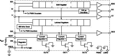
The PWM dimming range is the ratio of the brightest to dimmest light value, which equals the ratio of the PWM period to the minimum pulse width. In color-mixing applications, the combination of the dimming ratios for the component colors determines the number of hues that can be displayed. For example, the Allegro™ A6281 has a 10-bit PWM per LED channel, allowing 1,024 brightness levels. For a red/green/blue pixel, there are 1,0243, or over one billion, color combinations.
The PWM repetition rate should be faster than the eye can see, generally at least 200 Hz. For applications where a display may be photographed or filmed, the PWM period must be shorter than the exposure time of the camera. This may be 2 milliseconds or less, corresponding to a repetition rate of 500 Hz or more. With 1,024 time slots in each PWM interval, the clock must be 500 kHz or greater. The A6281 has an internal clock that can operate at 800 kHz, or it can be clocked externally at up to 5 MHz.Finally, LEDs vary with age. Although LEDs will last 50,000 to 100,000 hours, their brightness will gradually decrease over that time as the die degrades and the encapsulant loses transparency. In white LEDs, the phosphor also degrades, reducing brightness and causing a color shift. Since different colors are produced by different materials which degrade at different rates, the color balance changes as LEDs lose brightness. A closed-loop system using feedback from a light sensor to increase drive current over time can compensate for variations caused by aging as well as perform initial calibration and compensate for temperature effects.
It is often desirable to perform calibration, which is done infrequently, separately from refreshing the fast-changing image data. The A6281 has separate registers to hold image data, which controls the pulse width modulators, and calibration data, which controls 7-bit D/A converters that adjust the LED currents. Thus, color balance and day/night brightness can be set as needed using the DACs independently from displaying the image data, which PWMs the LEDs.
In a large, distributed system, such as a building façade display, it can be difficult to route a clock signal across the entire system. Integrating a local PWM oscillator at each pixel simplifies system design. Since the pixel PWM clocks are not synchronized, total peak currents are less than in a synchronized system. If synchronizing the drivers is desired, a string of A6281s can be clocked by a single external signal.
In large, building-size systems, the distance from one pixel to the next may be a meter or more. The A6281 has buffers to regenerate data and control signals to the next pixel on the cable. These features allow hundreds of A6281s to operate on hundreds of meters of cable.
Other features of the A6281 that simplify system design are:-
An integrated 5-V logic regulator, dropping the voltage from the LED supply, which can be up to 17 V. The higher LED supply voltage allows several LEDs of each color to be stacked for extra brightness.
-
Small package size: 3-mm x 3-mm QFN.
-
Wide temperature range (-40 to +85 C) plus thermal shutdown.
-
More current (150 mA per channel) than other 3-channel drivers for full visibility in daylight.
The A6281 is a leading example of modern LED drivers which precisely control LEDs and help compensate for their variation with temperature, aging, and operating current. Look for more advances in drivers as LEDs continue their progress.
AN296103