Guidelines for Designing a Concentrator for High-Current Sensing Applications with an Allegro Hall-Effect Sensor IC
By Cedric Gillet and Andreas Friedrich
Allegro MicroSystems, LLC
As with any semiconductor device, the integrated current sensing solutions that Allegro™ offers can be limited in the maximum allowable current and isolation voltage they can tolerate. Energy dissipation and package dimensions are the limiting parameters. For high-current applications (>200 A), Allegro recommends the use of a magnetic concentrator with a Hall-effect sensor IC (figure 1). The system consists of a ferromagnetic concentrator that surrounds the current conductor and is designed with a little window, called the air gap, into which the sensor IC is placed. The aim of this document is to provide basic guidelines for designing a high-current concentrator.
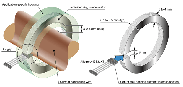
Figure 1. Typical high-current sensing system with concentrator.
Introduction
A concentrator focuses magnetic flux lines, which are generated by electrical current flowing through a conductor, at the center of the air gap, where the Hall-effect magnetic sensor IC is positioned. The efficiency of a concentrator (also referred to as a magnetic core), and thus of the current sensing system, depends crucially on the following factors:
- Core material
- Core dimensions
- Air gap
- Core geometry
The following sections detail each of these factors, one by one.
Concentrator material
The choice of the concentrator material is made by subtle compromises among its permeability, resistivity, and cost. To concentrate the magnetic flux lines on the sensing element, the core must not saturate at high current. Thus it must have a high permeability relative to air, but not as high as permanent magnet material in order to avoid undesirable residual magnetization after being exposed to high current, which generates measurement hysteresis. The families of iron alloys such as ferrosilicon (FeSi) or ferronickel (FeNi) are most commonly used for power applications because they exhibit a high permeability and so a high saturation point (figure 2).
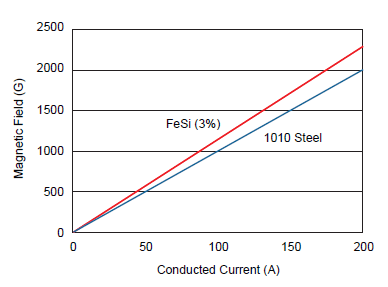
Figure 2. Core Gain for FeSi (3%) and 1010 Steel. For the same core, FeSi generates a higher gain slope (1 G (gauss) = 0.1 mT (millitesla)).
The drawback of irons is their low resistivity, making them vulnerable to eddy currents (induced reverse electric current), thus degrading the current measurement accuracy in the frequency domain. To minimize this effect is the reason why the irons have to be alloyed to less conductive materials, such as silicon. In addition, it is recommended to laminate the core using layers of typically 0.3 mm thickness, which will significantly reduce eddy currents (the thinner the layers, the smaller the eddy currents) (figure 3). Each layer must also be coated with silicon to even more efficient.
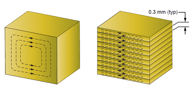
Figure 3. Eddy Currents in Bulk Material (left) and Laminated Material (right). Laminated material has reduced eddy currents.
Other materials, such as carbonyl irons, amorphous metals, or ferrite, may seem attractive at first sight but are not recommended today either because of degradation of their magnetic properties over time (carbonyl irons) or because of their larger magnetic hysteresis (amorphous metals). Even though the ferrites have a lower cost, and a higher resistivity (minimizing eddy currents), they also have a lower permeability and a quite-low saturation point, making them not really suitable for high-current applications.
Concentrator dimensions
Assuming a circular, ring-shaped core, its size is defined by the dimensions of its outside diameter (O.D.), its inside diameter (I.D.), and its thickness (T) (figure 4). All three define the area of the core cross section at the air gap.
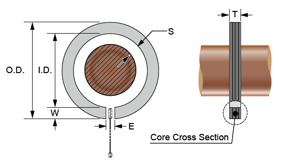
Figure 4. Concentrator Dimensions
Magnetic simulations that were run at a fixed air gap length (E) and cross-sectional area have demonstrated that the optimum core width (W) is around 3 to 4 mm, to obtain the best magnetic concentration (figure 5).
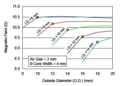
Figure 5. Magnetic Field versus Core Width (O. D. – I. D.). Magnetic flux density (B) was measured at the center of the air gap (1 G (gauss) = 0.1 mT (millitesla)).
Additional magnetic evaluations have shown that the larger the diameter of the core, the higher the saturation point will be. Similarly, the larger the cross section of the core, the more elevated the saturation point. It is important to note that the diameter of the concentrator (assuming a constant width, W, between O.D. and I.D.) does not significantly affect its magnetic gain, but only its saturation point (figure 6).
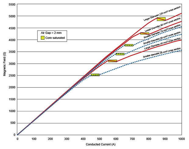
Figure 6. Effects of Core Cross Section and Diameter on the Magnetic Field Flux Density (B). Relative diameter does not significantly affect the magnetic gain, but does affect the magnetic saturation point of the core.
Obviously, the concentrator diameter and cross section should be as large as the application allows. Furthermore, it is recommended to leave a minimum 3 to 4 mm of spacing (S in figure 4) between the current conductor and the concentrator to make sure the concentrator does not saturate at higher currents.
Concentrator air gap
The length of the air gap (E) is the key parameter of the concentrator design because it directly defines the gain of the system. The smaller the air gap (at a constant cross-sectional area) the higher the gain. However, if the air gap is too narrow the residual magnetic hysteresis of the core becomes significant, thereby lowering the accuracy performance at smaller currents. The recommended air gap is between 3 and 5 mm. The air gap obviously has to be adjusted to the sensor package thickness. Figure 7 reports the different gains of a concentrator with varying air gap.
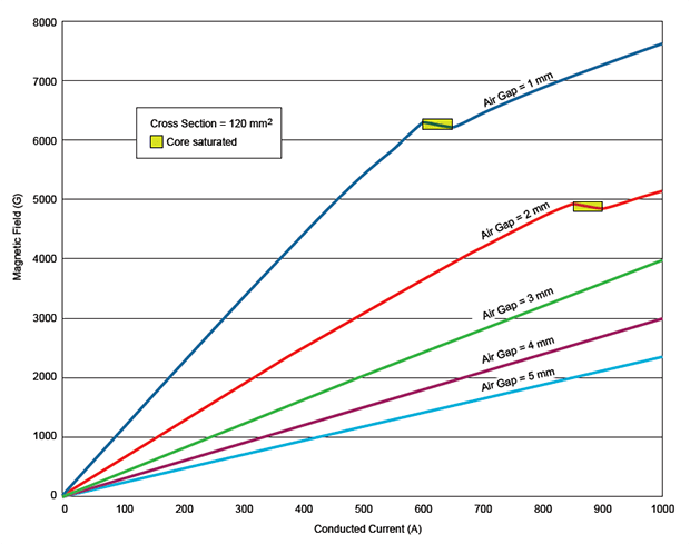
Figure 7. Effects of Air Gap on the Magnetic Field Flux Density (B). Smaller air gaps result in greater magnetic gain, but the saturation points that occur at the smaller air gaps limit current sensing range.
Concentrator geometry
As long as the concentrator focuses the magnetic flux lines onto the sensing element, the concentrator geometry will not have a huge impact on the system. Commonly, cores are circular to concentrate the flux lines in one direction and to avoid angle effects, but rectangular concentrators can be used as well. With rectangular cores, it is recommended to round the inner corners of the core to avoid magnetic concentration effects (figure 8). On the outside of the core, rounding is less relevant because those corners are further away from the conductor.
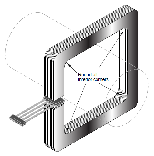
Figure 8. Rectangular Concentrator Configuration. The same design rules apply as with the circular ring concentrators. In addition, the interior corners, and optionally the outer corners, must be rounded to avoid angle effects.
Conclusion
The design of a concentrator for high-current sensing applications (>200 A) should be optimized by applying the following rules:
- The core should be made of FeSi or FeNi.
- The core must be laminated and coated with silicon material.
- The core diameter should be as large as the application allows, with a large solid material cross section (minimum 25 mm2).
- The concentrator width should be around 3 to 4 mm.
- Keep a minimum spacing distance of 3 to 4 mm, in all directions, between the core and the conductor.
- The air gap should be from 3 to 5 mm.
- Non-circular concentrator shapes must be as round as possible on the interior corners.
The Allegro linear sensor ICs in the KT package, for example the A1363LKT, are ideally suited to these high-current sensing systems.