Hot-Swap Testing Results for the A5977 and A5979 Microstepping DMOS Drivers
Introduction
Hot-swapping, disconnecting, or connecting power supply inputs and/or power outputs of an IC while in operation is
not recommended, but it is normal practice in some applications. One of these applications is in textile machines, where the motor and power supply leads can be connected and disconnected while the current is supplied to both motor windings. In this application, the IC motor outputs and
power supply are connected to the motor driver PC board (6 pins) via a switching relay arrangement.
This report outlines hot-swap test results for A5977 and A5979 stepper motor drivers. To duplicate the hot-swap conditions, we have selected an IC motor supply voltage (VBB) of 24 V and motor current of 1.5 A per winding for our tests. Testing was performed with different microstepping resolutions and with the following hot-swap methods:
- Hot-swapping between two sets of motors and power supplies
- Hot-swapping a single motor from on-line to off-line
- Hot-swapping between two sets of motors with motor driver always powered up
- Hot-swapping a single motor with motor driver always powered up
- Faulty conditions during single phasing of stepper motor
- Switching the power supply on-off with stepper motor terminals always connected
Objective
To evaluate the hot-swapping performance of the A5977 and A5979 microstepping DMOS driver ICs.
Experimental Setup
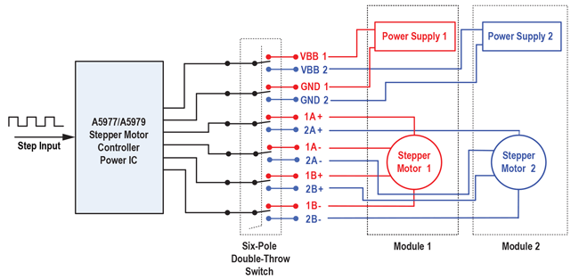
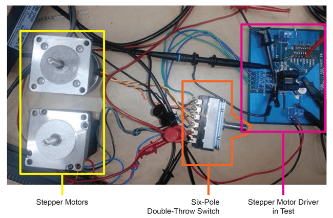
Figure 1 shows the test connections for hot-swapping the stepper motor driver (A5977/A5979). The experimental test prototype of the same has been developed in lab as shown in Figure 2. In this setup, a 6-pole, double-throw switch is used for hot-swapping between the motors and the power supply. Two power supplies of 100 W each and two stepper motors are connected on six poles of the switch as depicted in Figure 1. The evaluation board used is a standard A5977/79 socket board.
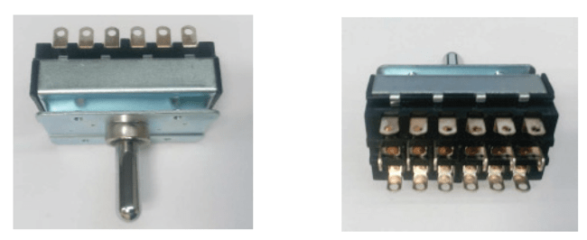
Figure 3 shows the front and rear view images of the 6-pole, double-throw switch used for development of the hot-swap testing setup.
Measurement of Parameters
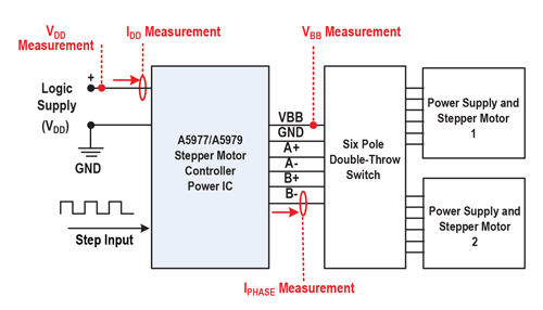
Figure 4 shows the typical setup for the measurement of various parameters during hot-swap testing. VDD and IDD represents the logic supply voltage and current, respectively.
Hot-Swap Test Results for the A5977/A5979 Microstepping Motor Driver ICs
The following section presents the evaluation of the A5977/A5979 stepper motor driver power ICs during various hot-swapping conditions. The various conditions of hot-swap testing are summarized as follows:
- Hot-swapping between two sets of motors and power supplies.
- Hot-swapping a single motor from on-line to off-line.
- Hot-swapping between two sets of motors with motor driver always powered up.
- Hot-swapping a single motor with motor driver always powered up.
- Faulty conditions during single phasing of stepper motor.
- Switching the power supply on-off with stepper motor terminals always connected.
The stepper motor driver has been tested multiple times for the above mentioned conditions. Following are the results observed at these conditions.
HOT-SWAPPING BETWEEN TWO SETS OF MOTORS AND POWER SUPPLIES
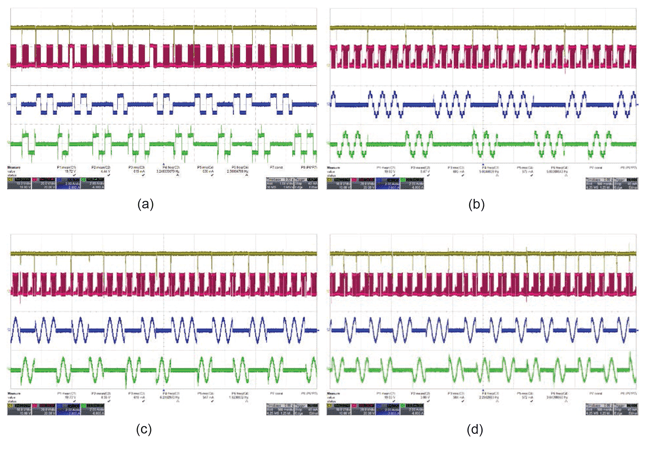
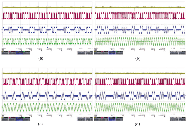
This case is the most basic case of hot-swapping in which the stepper motor driver is hot-swapped between the two sets of a motor and power supply combination. A 6-pole, double-throw switch is used for hot-swapping the motor driver between the two stepper motors and power supply sets. Figure 5 (a) through (d) shows the results observed during the full-, half-, quarter-, and eighth-step (A5977) modes, respectively. This test has been carried out on 20 ICs with a minimum of 100 hot-swaps. The driver operated normally with no change in performance after each hot-swap.
HOT-SWAPPING A SINGLE MOTOR FROM ON-LINE TO OFF-LINE
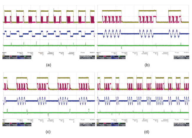
In this case, a single stepper motor and power supply set is connected to the motor driver; therefore, all the six lines, including VBB, GND, OUT1A, OUT1B, OUT2A, and OUT2B are connected and disconnected during hot-swapping. Figure 6 (a) through (d) shows the results observed during the full-, half-, quarter-, and eighth-step (A5977) modes, respectively. This test has been carried out on 20 ICs with a minimum of 100 hot-swaps. The driver operated normally with no change in performance after each hot-swap.
HOT-SWAPPING BETWEEN TWO SETS OF MOTORS WITH MOTOR DRIVER ALWAYS POWERED UP
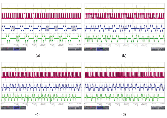
In this case, two stepper motors are hot-swapped while the power supply is always connected to the motor driver. Therefore, only four lines, including OUT1A, OUT1B, OUT2A, and OUT2B, are connected and disconnected during hot-swapping. Figure 7 (a) through (d) shows the results observed during the full-, half-,
quarter-, and eighth-step (A5977) modes, respectively. This test has been carried out on 20 ICs with a minimum of 100 hot-swaps. The driver operated normally with no change in performance after each hot-swap.
HOT-SWAPPING A SINGLE MOTOR WITH MOTOR DRIVER ALWAYS POWERED UP
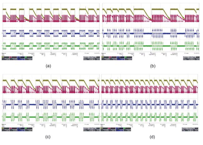
In this case, a single stepper motor is hot-swapped while the power supply is always connected to the motor driver. Therefore, only four lines, including OUT1A, OUT1B, OUT2A, and OUT2B, are connected and disconnected during hot-swapping. Figure 8 (a) through (d) show the results observed during the full, half, quarter, and eighth step (A5977) modes, respectively. This test has been carried out on 20 ICs with a minimum of 100 hotswaps. The driver operated normally with no change in performance after each hot-swap.
FAULTY CONDITIONS DURING SINGLE PHASING OF STEPPER MOTOR
In this case, one phase of the stepper motor is connected and disconnected in hot with power supply always connected to the motor driver. Therefore, in this case, a single line from any of the four lines, i.e. OUT1A, OUT1B, OUT2A, and OUT2B, are connected and disconnected during hot-swapping. Figure 9 (a) through (d) shows the results observed during the full-, half-, quarter-, and eighth-step (A5977) modes, respectively. This test has been carried out on 20 ICs with a minimum of 100 hot-swaps. The driver operated normally with no change in performance after each hot-swap.
FAULTY CONDITIONS DURING SINGLE PHASING OF STEPPER MOTOR
In this case, one phase of the stepper motor is connected and disconnected in hot with power supply always connected to the motor driver. Therefore, in this case, a single line from any of the four lines, i.e. OUT1A, OUT1B, OUT2A, and OUT2B, are connected and disconnected during hot-swapping. Figure 10 (a) through (d) shows the results observed during the full-, half-, quarter-, and eighth-step (A5977) modes, respectively. This test has been carried out on 20 ICs with a minimum of 100 hot-swaps. The driver operated normally with no change in performance after each hot-swap.
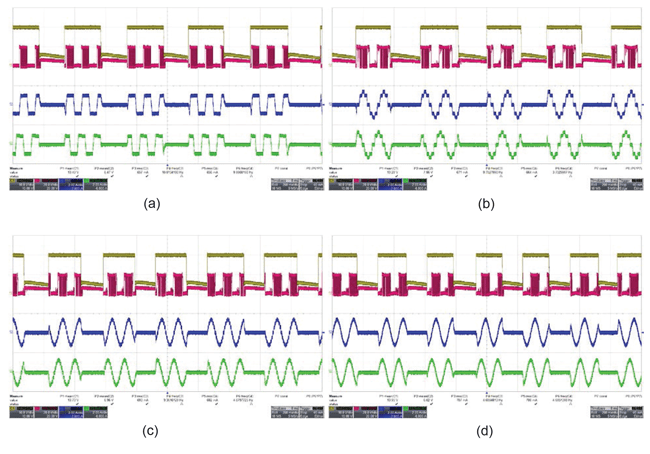
step, and (d) eighth-step (A5977) modes, showing the DC bus voltage (VBB) (yellow), phase voltage (VPHASE) (pink),
and stepper motor phase currents (IPHASE1 and IPHASE2) (blue and green).
CONCLUSION
A rigorous hot-swap testing of the A5977 and A5979 stepper motor drivers has been carried out and presented in this report. At least 20 ICs have been tested 100 times each for all 6 mentioned hot-swapping conditions (6 conditions × 20 ICs × 100 times each = Total 12000 events).
This hot-swap testing has also been performed on a single device for four different stepping modes, i.e. full-step, half-step, quarter-step, and eighth-step (A5977) modes. The driver operated normally with no change in performance after each hot-swap.
We can conclude that the A5977 and A5979 have robust hot-swap performance under the conditions presented in this report.