Specialized Motor Drivers in Industrial Automation

Motors are the backbone for the industrial automation market as most of the applications involve movement or rotation. Applications include robots, conveyer systems, part manipulators, material handlers, fans, arm tooling, inspection machines, linear motion actuators, and many more. An overall ecosystem of sensors, controllers, and actuators is needed to implement such applications. Specialized motors such as brushed DC, brushless DC, and stepper motors are invariably used in industrial automation based on the
specific application need. This article focuses on the specialized motors in low-to-mid-power ranges, which have their own challenges and specific needs in a variety of applications.
Automation Market Trends
The automation market has historically been a 12 V market with safety needs to ensure system reliability and reduce overall maintenance costs. However, several key trends are emerging in to achieve higher functional performance, provide higher power throughput, improve system efficiency, and reduce cost while meeting industrial safety standards.
-
Shift to 48 V – A shift to 48 V drivetrains reduces current and power dissipation by 4 compared to a traditional 12 V drive This increases system payload to handle heavier loads and perform more demanding tasks, like lifting heavier components. Additionally, lower current requirements means less expensive wiring, less power dissipation as heat, and overall long-term cost savings by consuming less energy.
-
Innovative integration – Many solutions combine the motor drive, encoding, and braking systems into a single unit to simplify design, reduce component count, minimize wiring complexity, and offload computing power from the microprocessor. Integrated system design approaches and deployment concepts, such as daisy-chain communication, allow for multiple robotic units to communicate
- Safety first – International standards such as UL2595 and UL1740 guide general safety requirements for battery powered equipment, and ISO standards such as ISO13482 and ISO10218 target safety requirements for industrial robots. However, as robots are becoming more sophisticated and autonomous, safety in hardware design remains critical for occurrences when sensors and robotic perception fails. Therefore, rigorous updates to standards like ISO10218, IEC61508, and ANSI/ RIA R15.08 are expected to emphasize safety needs in automation.

Specialized Motor Needs and Challenges
A servo mechanism is commonly used in many automation applications which involves a rotary actuator or a linear actuator for precise control of angular or linear position, velocity, and acceleration. It differs from regular motors because it incorporates
a closed-loop feedback mechanism to ensure that the output shaft reaches the desired position accurately. Brushed DC, brushless DC (BLDC), and stepper motors are commonly used in servo motor drives for low-to-mid-power applications such as robotics, linear transport systems, and multi-axis servo drives.
Brushed DC Motor
Brushed DC motors use carbon brushes and a mechanical commutator arrangement for the operation of a motor, as shown in Figure 1. The primary advantage of these motors is the lower cost of motor and electronic components and the low complex ity involved in design of the electronic control system. However, due to the mechanical brush arrangement, brushed DC motors suffer from sparking and noise issues, which eventually limits their use in higher power and noise-sensitive applications. This type of motor requires frequent maintenance and has a shorter lifespan. Typically, brushed DC motors are used in linear motion, conveyors, and part manipulators.
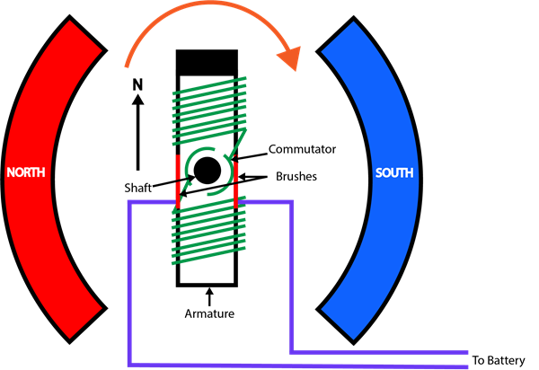
Figure 1: Brushed DC motor diagram
A brushed DC motor can be driven by two half-bridge drivers, a full-bridge driver, or multi-full bridge drivers with integrated or external FETs. Depending on the safety and system architecture needs, drivers with extra protection and diagnostics help ensure system reliability and minimize external hardware component requirements. Furthermore, a half-bridge or BLDC motor driver can optionally integrate high-accuracy current sense to provide closed loop feedback for position accuracy and to reduce the overall system solution size.
Allegro provides a variety of DC motor solutions as shown in Table 1.
Table 1: Allegro MicroSystems DC motor solutions in robotics
|
Category |
Power Stage |
Solution |
Description |
Other Features |
|
Half-Bridge |
Gate Driver |
|
100 V half-bridge gate driver |
Small 3�3 mm solution for compact form factors, such as robotic joints |
|
|
80 V half-bridge gate driver with diagnostics |
Robust solution supporting –18V transients, advanced diagnostics and safety protections |
||
|
|
80 V half-bridge gate driver with diagnostics, drain monitoring |
Integrated control and monitors with single external resistor to reduce MCU bandwidth |
||
|
Brushed DC Motor |
Integrated Stage Power |
40 V, 3 A, integrated full- bridge DC motor driver |
Resistor adjustable gate drive and peak current limit, functional safety- quality managed |
|
|
Gate Driver |
50 V, full-bridge gate driver with current sense |
Brushless DC Motor
Brushless DC motors are better suited for applications which require lower noise and higher performance to support less cost sensitive high-speed or high-torque operations. These applications include robot joints, fans, material handlers, conveyors, part manipulators, and linear motion. These motors offer advantages such as high efficiency, high flux density, low mainte- nance requirement, low electromagnetic interference (EMI), high ruggedness, and a wide range of speed control. Unlike brushed DC motors, robot position information must be used for control of the electronic commutation of the BLDC motor. This rotor position is typically sensed via a Hall sensor (typically Hall latches or Position/Angle Sensor) or an encoder.
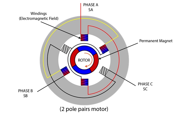
Figure 2: Brushless DC motor diagram
BLDC motor control is typically classified into two types of position feedback: sensored and sensorless. Sensored BLDC motors rely on Hall effect sensors, position sensors, or angle sensors to directly measure the rotor’s position. These sensors are typically embedded within the motor and generate signals corresponding to the magnetic field orientation, indicating the rotor’s angular position. This information is then fed to the motor controller to energize the appropriate stator windings.
The key advantages of the Sensored control algorithm are precise commutation, smooth low-speed operation, simplified control and reliable startup as shown in Figure 3. However, due to additional requirement of sensors, extra cost is required as well as ensuring their reliability in noisy environments. The high-speed operation of the motor is limited by the update rate of the position sensor.
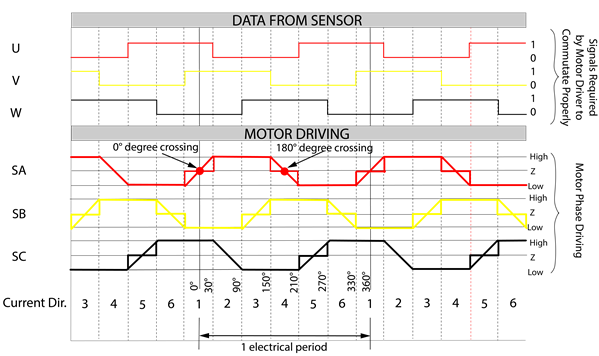
Figure 3: Sensored BLDC control using external Hall sensor feedback
The sensorless BLDC motors estimate the rotor’s position indirectly by monitoring the back-emf (electromotive force) gener- ated by the motor windings. The back-emf voltage varies with rotor position, providing information about its angular displace- ment. Various sensorless techniques exist, including zero-crossing detection, back-emf integration, and observer-based methods to accurately detect the rotor position as shown in Figure 4. This control technique offers an improved reliability per- formance due to removal of Hall-sensors which eliminates the problems associated with sensor vibrations and wire harness- ing, as well as reduced cost with a potential to reach higher speeds. However, the overall algorithm complexity increases, which in turn increases the controller cost and a high dependence on motor parameters need extra calibration. Also, at lower speeds, the estimation of back-emf is challenging which leads to startup issues and poor performance at lower speeds. While sensorless control is cost effective, has a smaller form factor, and offers increased reliability.
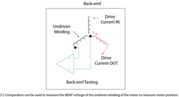
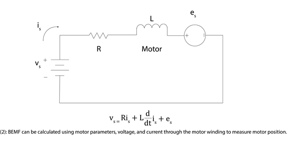
Figure 4: Various techniques for measuring back-emf of a motor winding
The algorithm complexity in sensorless brushless DC motors also depends on the type of back-emf as shown in Figure 5. The control algorithm for trapezoidal back-emf BLDC motors is simpler to implement compared to sinusoidal back-emf BLDC motors. Trapezoidal back-emf BLDC motors are preferred in higher speed and higher torque applications where noise is not the primary constraint, whereas sinusoidal back-emf BLDC motors are used for more sophisticated and high-performance applications. There are further specialized algorithms such as the field-oriented control (FOC) for improving the efficiency of the sinusoidal back-emf BLDC motor.

Figure 5: Motor control algorithms are based on the motor’s back-emf
A Brushless DC motor can be driven by three half-bridge drivers or a 3-phase BLDC driver with integrated or external FETs. Depending on the safety and system architecture needs, drivers with extra protection and diagnostics help ensure system reli- ability and minimize external hardware component requirements. Additionally, a half-bridge or BLDC motor driver can option- ally integrate high-accuracy current sense amplifiers to further reduce BOM cost and reduce the overall system solution size.
Furthermore, code-free BLDC drivers offer integrated sensored or sensorless motor control solutions to offload MCU resources and provide higher efficiency compared to traditional microcontrollers providing PWM signals to control the MOS- FETs.
Allegro provides a wide selection of BLDC motor solutions as shown in Table 2.
Table 2: Allegro MicroSystems solutions for Brushless DC motors in robotics
|
Category |
Power Stage (Control) |
Solution |
Description |
Other Features |
|
Half-bridge |
Gate Driver |
100 V half-bridge gate driver |
Small 3×3 mm solution for compact form factors, like robotic joints |
|
|
80 V, three-phase BLDC gate driver with safety, diagnostics, & low-side current sense |
Robust solution supporting –18 V transients, integrated current sense, advanced diagnostics and safety protections |
|||
|
Brushless DC motor |
Gate Driver |
|
80 V, three-phase BLDC gate driver with safety, diagnostics, & 3× low-side current sense |
Robust & integrated solution supporting –18 V transients, advanced diagnostics and safety protections |
|
Integrated FET (Sensorless Sine) |
18 V, 3 A, sensorless BLDC fan driver |
Low-power solution for efficient BLDC motor control in 4 mm × 4 mm package |
||
|
Gate Controller (Sensorless Sine) |
50 V, sensorless sinusoidal fan controller |
Low-power solution for efficient BLDC motor control in 4 mm × 4 mm package |
||
|
Integrated FET (Sensorless FOC) |
20 V, 2 A, sensorless FOC BLDC motor driver |
Single-chip solution for sensorless FOC BLDC solution with only 1 low side shunt required |
||
|
Gate Controller (FOC) |
50 V, ultra-low noise FOC motor controller |
High-power & efficient BLDC solution with only 1 low side shunt required |
||
|
Integrated FET (Sensorless Trapezoidal) |
50 V, sensorless trapezoidal BLDC motor driver |
Fast startup and motor speed in small 5×5 mm solution |
||
|
Gate Controller (Sensored Trapezoidal) |
50 V, sensored trapezoidal BLDC motor controller |
Integrated trapezoidal control and current limiting to reduce MCU bandwidth |
Stepper Motor
Stepper motors are typically used in low-speed, low-power, position control applications. The key advantages of stepper motors include higher holding and low-speed torque, high reliability, and lower cost compared to servo motors. However, stepper motors are not very efficient motors; therefore, it is not economical to use them for higher power applications.
Moreover, since they use an open loop control, these systems do not have missing step or stall condition information. There- fore, stepper motors are used in non-critical and cost-sensitive applications where they still need position accuracy, such as machine tools.
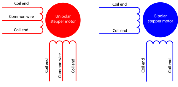
Figure 6: Unipolar motor vs. bipolar stepper motor wiring connection
Among various categories of stepper motors, unipolar and bipolar stepper motors are most common as shown in Figure 6. Unipolar stepper motors are used in high-speed, high-torque applications, but microstepping is required to implement open- loop position control. On the other hand, bipolar stepper motors are becoming more common due to easy current control and better low-speed performance.
A stepper can be driven by a dual H-bridge driver or a stepper driver with dedicated step control using integrated or exter- nal FETs. Depending on the safety and system architecture needs, drivers with extra protection and diagnostics help ensure system reliability and minimize external hardware component requirements. Additionally, a stepper driver can optionally integrate robust protection features like stall detection, open loads, or short to battery and ground when performing position control with large payloads.
Table 3: Allegro MicroSystems solutions for stepper motors in robotics
|
Category |
Power Stage (Control) |
Solution |
Description |
Other Features |
|
Stepper Motor |
Integrated Driver |
40 V, 2.8 A, stepper motor driver with microstepping |
Automatic decay modes to provide position control with lowest audible noise |
|
|
Gate Driver |
50 V, stepper gate driver with microstepping |
Enable high power stepper motors for position control & low audible noise |
Allegro provides a variety of stepper DC motor solutions as shown in Table 3.
Servo Motor Drive
Servo motor drives are used for accurate position and speed control in industrial automation applications. Servo motor drive involves a closed-loop position and speed control with the implementation of encoder feedback to allow real-time adjustment of speed and position for ensuring accurate and stable motion even in dynamic loading scenarios. Traditionally, brushed DC motors have been used in servo drives, but nowadays, BLDC motors are more popular in servo applications. Key advantages of the servo driver are the wide speed range, fast response, smooth control, high reliability, accurate posi- tion and speed control, high energy efficiency, easy integration, and ease of synchronization for multi-axis control. Servo motor applications are similar to BLDC motors but are preferred where precision and timing are crucial. These include precise robots, material handlers, part manipulators, linear motion control systems, and many more. Figure 1 shows a block diagram of a servo motor drive.
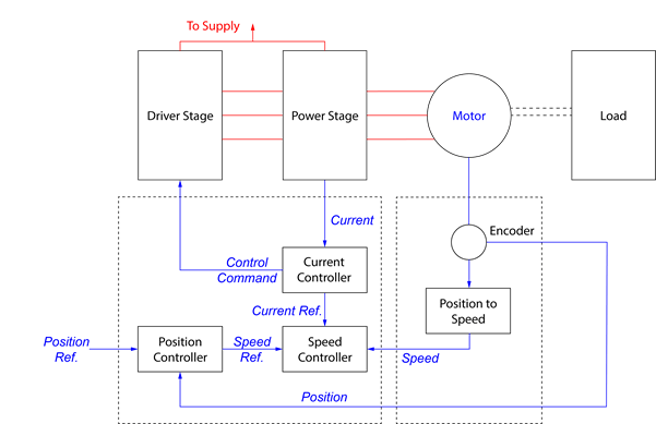
Figure 7: Servo motor drive
The control loop implementation of servo motor involves using multiple sensor feedback loops, which creates higher main- tenance requirements and environmental sensitivity factors. The complexity further increases with multi-axis control, which requires a high-speed microprocessor to communicate with and control two or more servo motors in real time. These factors impact the overall implementation, safety and maintenance cost of the drive system. However, servo motors remain a popular choice for industrial automation applications due to the high performance, precise position control, and quick response time.
Allegro Motor Driver Portfolio for Industrial and Factory Automation
Allegro offers a wide range of motor driver solutions with options of integrated power stage or the gate driver stage. Devices with integrated power stage can handle typical motor currents up to ~2 to 3 A, whereas gate drivers can be used to drive external MOSFETs supporting higher power depending upon the gate current strength.
For more detailed application information about different gate drivers, visit allegromicro.com, and see the following applica- tion notes on stepper decay and Hall-based BLDC gate drivers.